
Montero Sport XLS 4WD V6-3.5L SOHC (2002)
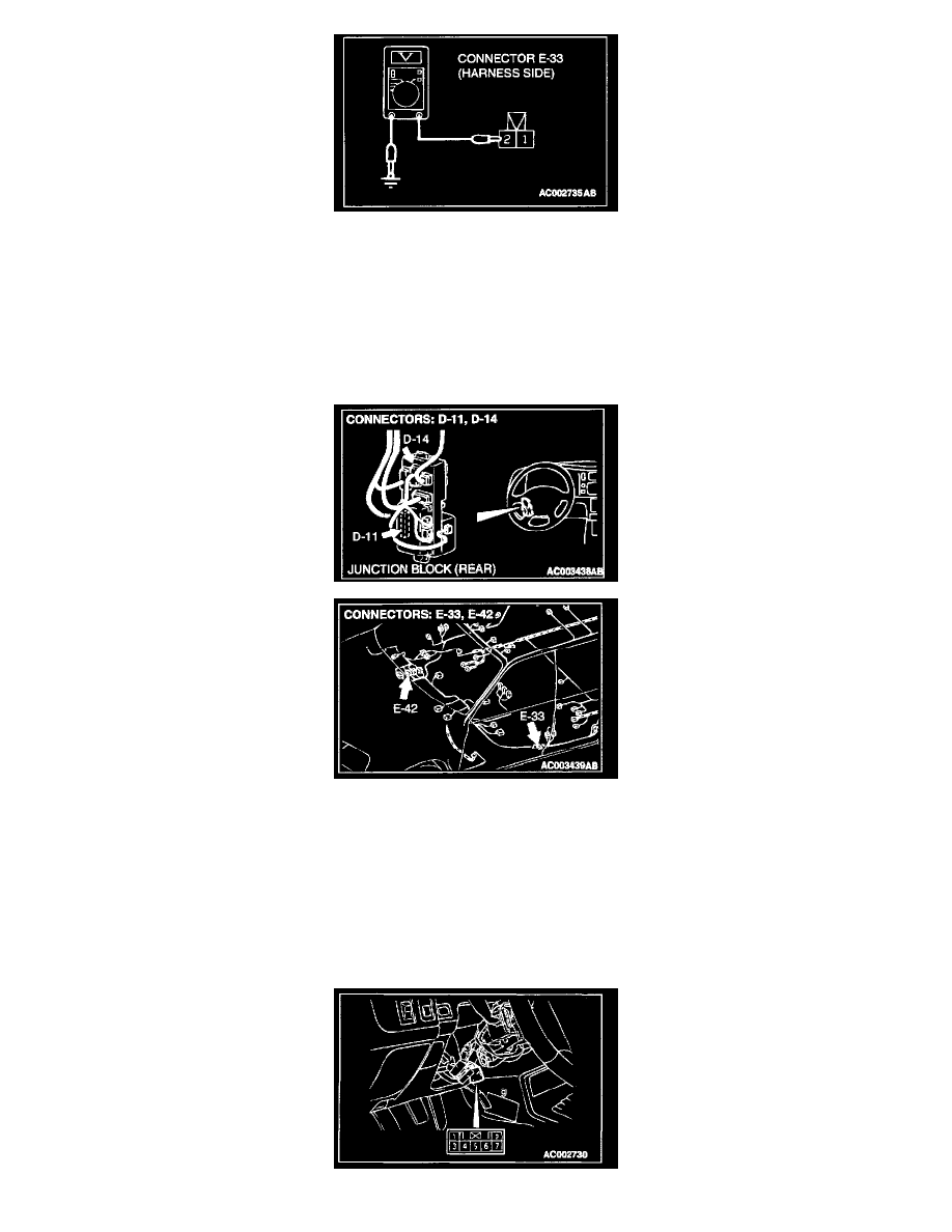
STEP 6. Check the driver's side door switch connector E-33 input circuit
1. Disconnect the driver's side door switch connector E-33 and the harness side.
2. Measure the voltage between terminal 2 and ground.
Q: Is the voltage approximately 5 volts?
YES: There is no action to be taken.
NO: Go to Step 7.
STEP 7. Check the harness wires between driver's side door switch connector E-33 and ETACS-ECU connector D-11.
NOTE: After inspecting junction block connector D-14 and intermediate connector E-42, inspect the wire. If junction block connector D-14 and
intermediate connector E-42 are damaged, repair or replace them. Refer to Harness Connector Inspection.
Q: Are the harness wire between driver's side door switch connector E-33 and ETACS-ECU connector D-11 in good condition?
YES: Go to Step 8.
NO: Repair heathenism check that the malfunction is eliminated.