
Montero Sport XLS 4WD V6-3.5L SOHC (2002)
STEP 16. Check the input signal from the fusible link number 6.
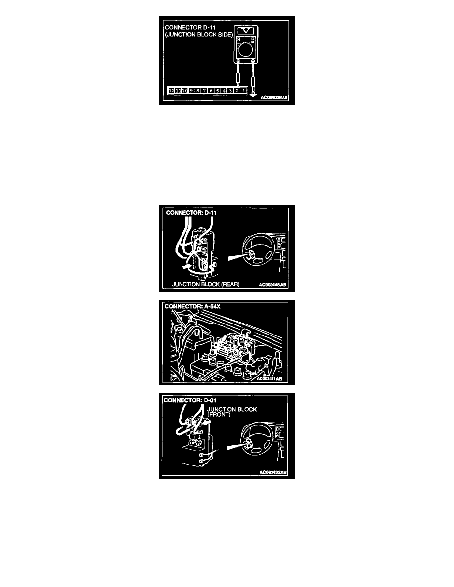
1. Remove the ETACS-ECU and measure at the junction block side (connector D-11).
2. Measure the voltage between terminal number 2 and body ground.
-
Voltage should be approximately 12 volts (battery positive voltage).
Q: Is the voltage approximately 12 volts (battery positive voltage)?
YES: Check that the malfunction eliminated.
NO: Go to Step 17.
STEP 17. Check the harness wire between ETACS-ECU connector D-11 and fusible link number 6.
NOTE: After checking junction block connector D-01 and IOD storage connector A-54X, check the wires. If junction block connector D-01 and IOD
storage connector A-54X are damaged, repair or replace them. Refer to Harness Connector Inspection.
Q: Are the harness wire between ETACS-ECU connector D-11 and fusible link number 6?
YES: Go to Step 18.