
Montero SR 4WD V6-3.5L DOHC (1995)
Idle Speed/Throttle Actuator - Electronic: Component Tests and General Diagnostics
NOTE: For testing of the harness and idle control system, see the Diagnostic Charts for the Non-Trouble Code Chart for the Idle Air Controller
(Stepper Motor) System.
IDLE AIR CONTROL MOTOR (STEPPER MOTOR) TESTING
Checking Operation Sound
1. Check that the operating sound of the stepper motor can be heard from the idle air control motor assy. when the ignition switch is turned to the ON
position (without starting the engine).
2. If no operating sound can be heard, check the stepper motor drive circuit. (If the circuit is good, a defective stepper motor or engine control
module is suspected).
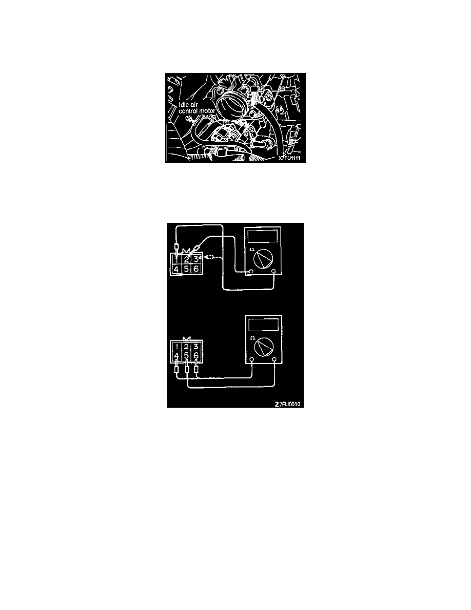
Checking Coil Resistance
1. Disconnect the idle air control motor connector and connect the special tool (test harness).
2. Measure the resistance between terminal (2) (White clip of the special tool) of the connector at the idle air control motor side and terminal (1) (red
clip) or terminal (3) (blue clip).
Standard value: 28-33 ohms [at 20°C (68°F)]
3. Measure the resistance between terminal (5) (green clip of the special tool) of the connector sat the idle air control motor side and terminal (6)
(yellow clip) or terminal (4) (black clip).
Standard value: 28-33 ohms [at 20°C (68°F)]