
Montero SR 4WD V6-3.5L SOHC (1997)
Wheel Speed Sensor: Testing and Inspection
Wheel Speed Sensor
Output Voltage Check
OUTPUT VOLTAGE MEASUREMENT
1. Check that the clearance between the wheel speed sensor and the rotor is within the standard value of 0.2-1.0 mm (0.008-0.039 inches).
2. Raise up the wheels and release the parking brake.
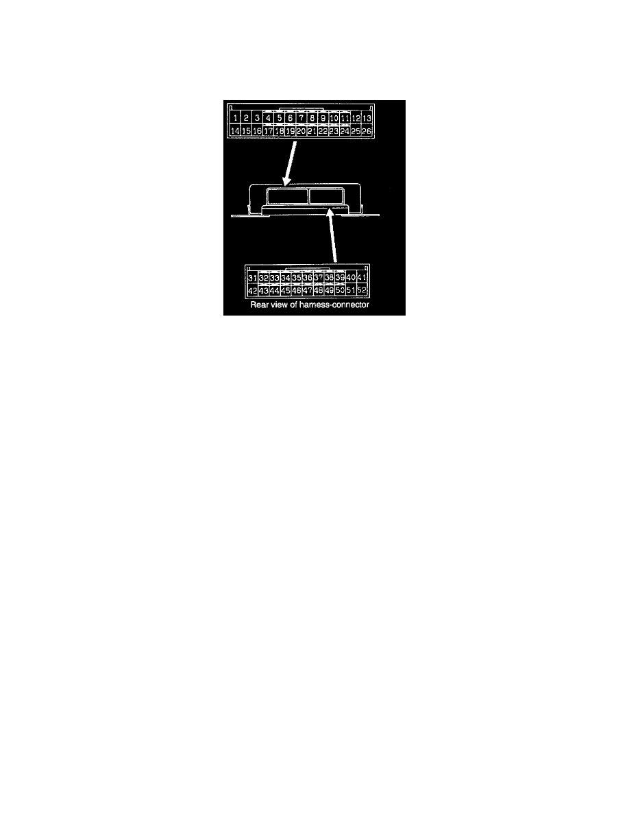
3. Disconnect the ABS-ECU connector and inspect the connector at the harness side.
CAUTION: Be sure to remove the connector double lock and insert the probe into the harness side. Inserting it into the terminal side will result
in a bad connection.
4. Rotate the wheel by hand to be measured at approximately 1/2-1 rotations per second and check the output voltage using a voltmeter (AC mV
range) or an oscilloscope. Measure at the following terminals:
a. The front LH sensor corresponds to terminal Nos. 7 (+) and 20 (-)
b. The front RH sensor corresponds to terminal Nos. 10 (+) and 23 (-)
c. The rear LH sensor corresponds to terminal Nos. 9 (+) and 22 (-)
d. The rear RH sensor corresponds to terminal Nos. 8 (+) and 21 (-)
NOTE: The output voltage when measured with a volt meter is 70 mV or more. When measured with a oscilloscope, 200 mV peak-to-peak or
more.
5. If the output voltage is lower than the above values, the reason could be as follows:
-
Excessive clearance between the wheel speed sensor pole piece and the rotor.
-
Malfunction of wheel speed sensor. Adjust the wheel speed sensor or replace if necessary.