
Montero SR 4WD V6-3.5L SOHC (1997)
STEP 3. Measure the applied voltage.
-
Throttle position sensor connector: Disconnected
-
Engine control module connector: Connected
-
Ignition switch: ON
Voltage (V): 4.8 - 5.2
OK: STOP
NG: Replace the engine control module.
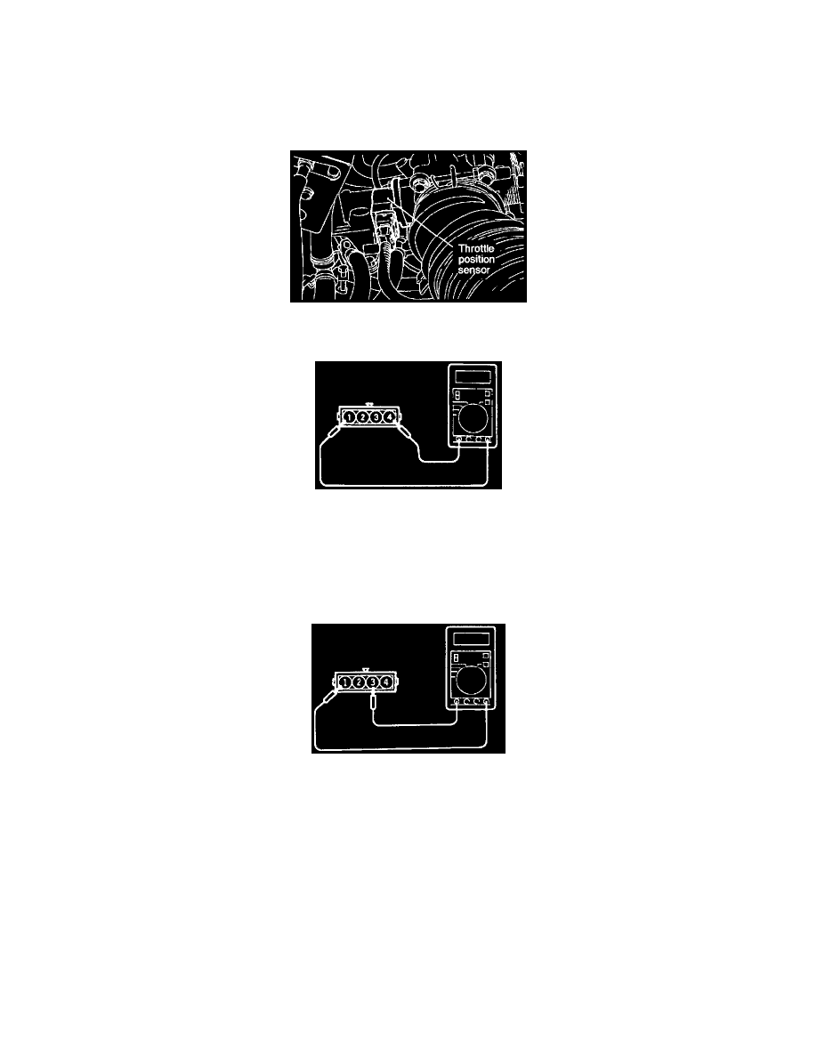
THROTTLE POSITION SENSOR CHECK
(1) Disconnect the throttle position sensor connector.
(2) Measure the resistance between terminal (1) (sensor ground) and terminal (4) (sensor power).
Standard value: 3.5 - 6.5K Ohm
(3) Connect a pointer type ohmmeter between terminal (1) (sensor ground) and terminal (3) (sensor output).
(4) Open the throttle valve slowly from the idle position to the full open position and check that the resistance changes smoothly in proportion with
the throttle valve opening angle.
(5) If the resistance is outside the standard value, or fails to change smoothly, replace the throttle position sensor.
TPS installation torque: 2.0 Nm (1.5 ft.lbs.)