
Montero SR 4WD V6-3.5L SOHC (1997)
a. Upper arm installation.
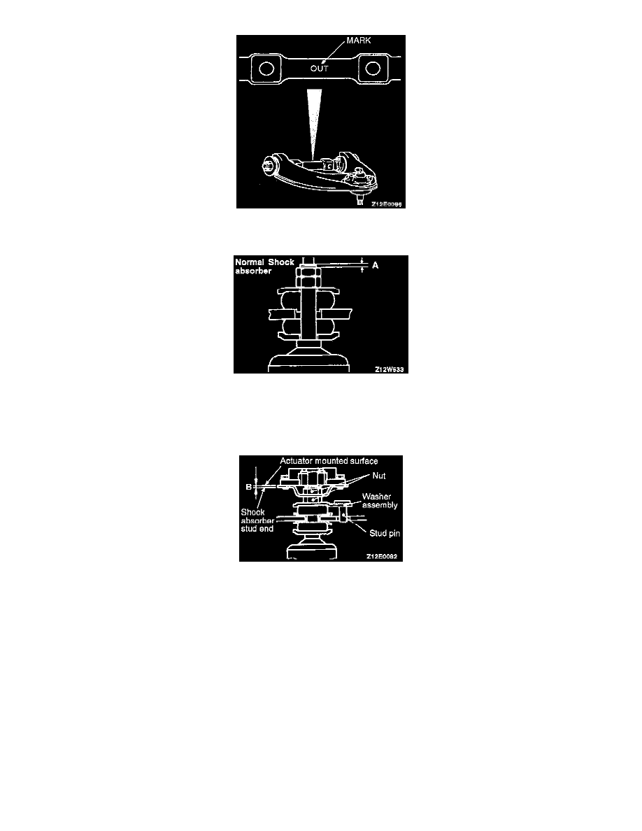
Install the upper arm so that the "OUT" mark on the upper arm shaft is facing toward the outside of the vehicle.
b. Shock absorber/actuator (vehicles with remote controlled variable shock absorber) installation.
Tighten the shock absorber installation nut so that the dimensions shown in the illustration (A and B) are at the standard values.
Standard value:
A: 1 - 2 mm (.04 - .08 inch)
B: 1.5 - 2.5 mm (.06 - .10 inch)
CAUTION: When tightening the nut, be careful not to bend the stud pin of the washer assembly.
c. Operational steps after installation as follows:
1. Front wheel alignment inspection and adjustment.
2. Bleed brake line.