
Montero SR 4WD V6-3.5L SOHC (1997)
Transmission Position Switch/Sensor: Description and Operation
OPERATION
-
The ignition switch-ST inputs HIGH signals to the engine control module during engine cranking. The engine control module regulates fuel
injection during starting, etc. based on those signals.
-
When the ignition switch is set to START, the battery positive voltage during engine cranking is applied to the engine control module by way of
the ignition switch and the park/neutral position switch, and the engine control module thus detects the fact that the engine is cranking. Note that
battery positive voltage is not applied to the engine control module if the selector lever is in a position other than P or N.
-
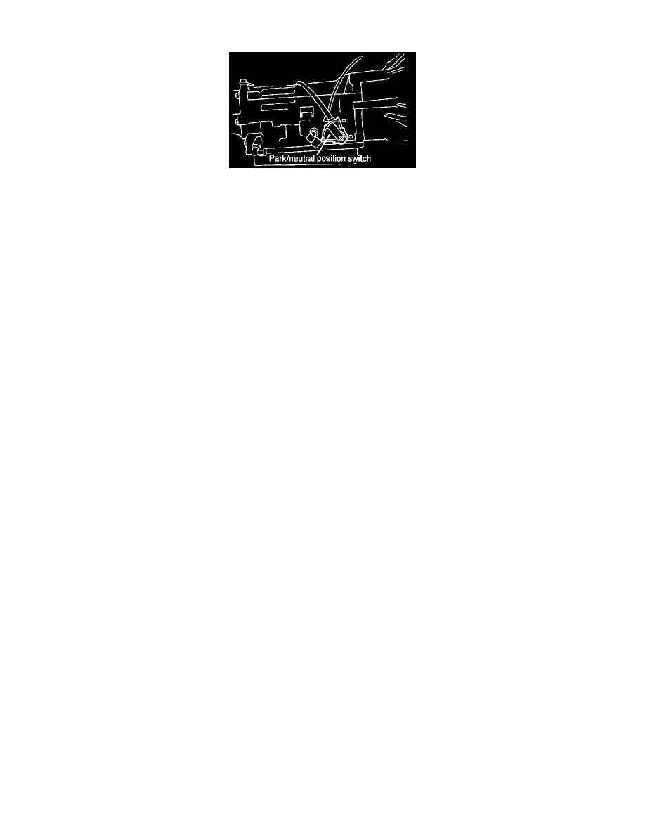
The park/neutral position switch functions to convert the voltage to HIGH level or LOW level depending upon whether the selector lever is in the
P or N position or is at some position other than P or N, and inputs the result to the engine control module. The engine control module, based upon
those signals, then regulates the operation of the idle air control motor.
-
Battery positive voltage inside the engine control module is applied via the resistance to the park/neutral position switch. When the selector lever
is placed in the P or N position, continuity is created, between the engine control module's park/neutral position switch terminal and the ground via
the starter motor, and the terminal voltage becomes low.