
Montero XLS 4WD V6-3.5L SOHC (2001)
NOTE: After inspecting joint connector D-116, intermediate connector E-111 and junction block connectors D-208 and D-212, inspect the wire. If
joint connector D-116, intermediate connector E-111 and junction block connectors D-208 and D-212 are damaged, repair or replace them. If the
connector has been repaired or replaced, go to Step 8.
Q: Is any harness wires between ignition switch (IG2) and buzzer connector E-107 damaged?
YES: Repair them and then go to Step 8.
NO: Go to Step 6.
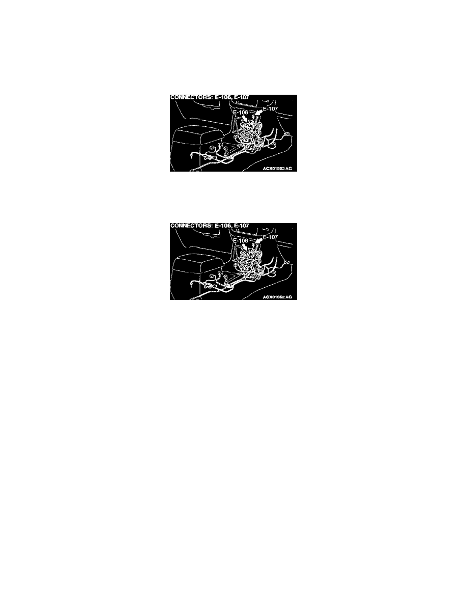
STEP 6. Check the buzzer connector E-107 and the ABS-ECU connector E-106.
Q: Are any of the connectors damaged?
YES: Repair it and then go to Step 8.
NO: Go to Step 7.
STEP 7. Check the harness wires between ABS-ECU connector E-106 and buzzer connector E-107.
Q: Is the wire between ABS-ECU connector E-106 and burner connector E-107 damaged?
YES: Repair it and then go to Step 8.
NO: Go to Step 8.
STEP 8. Check symptoms
1. Apply a chock to the wheel.
2. Start the engine.
3. When 120 seconds or more have been elapsed since the engine was started, release the parking brake lever and fully depress the brake pedal
repeatedly 15 to 20 times within 10 seconds.
Q: Does the buzzer sound?
YES: This diagnosis is complete.
NO: Start over at Step 1.
Inspection Procedure 4: the Buzzer Does Not Stop Sounding
INSPECTION PROCEDURE 4: The buzzer does not stop sounding.
Buzzer Circuit