
Montero XLS 4WD V6-3.5L SOHC (2001)
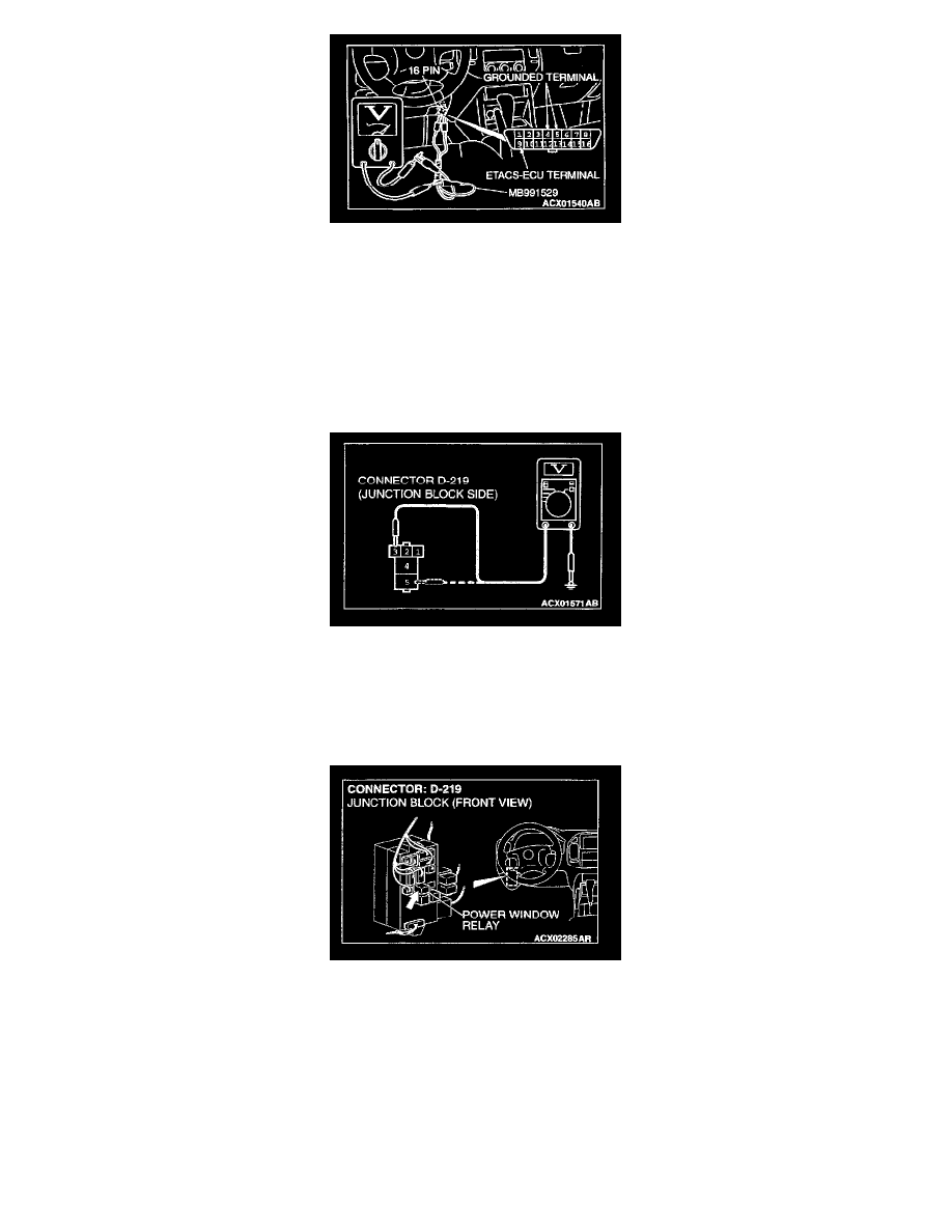
1. Use special tool MB991529 to connect a voltmeter between ground terminal 4 or 5 and ETACS-ECU terminal 9 of the data link connector.
2. Check that the voltmeter indicator deflects once when the input signal enters.
Q: Does the voltmeter indicator deflect?
YES: Go to Step 4.
NO: Check the ignition switch (IG1) input circuit. Refer to Inspection Procedure.
STEP 4. Check the power window relay power supply circuit at the power window relay connector D-219.
1. Disconnect the power window relay connector D-219 and measure at the junction block side.
2. Measure the voltages between terminal 3, 5 and ground.
Q: Are the voltages approximately 12 volts (battery positive voltage)?
YES: Go to Step 7.
NO: Go to Step 5.
STEP 5. Check the power window connector D-219 for damage.
Q: Is power window connector D-219 in good condition?
YES: Go to Step 6.
NO: Repair or replace it. Refer to Harness Connector Inspection. The power windows should work normally.