
Montero XLS 4WD V6-3.5L SOHC (2001)
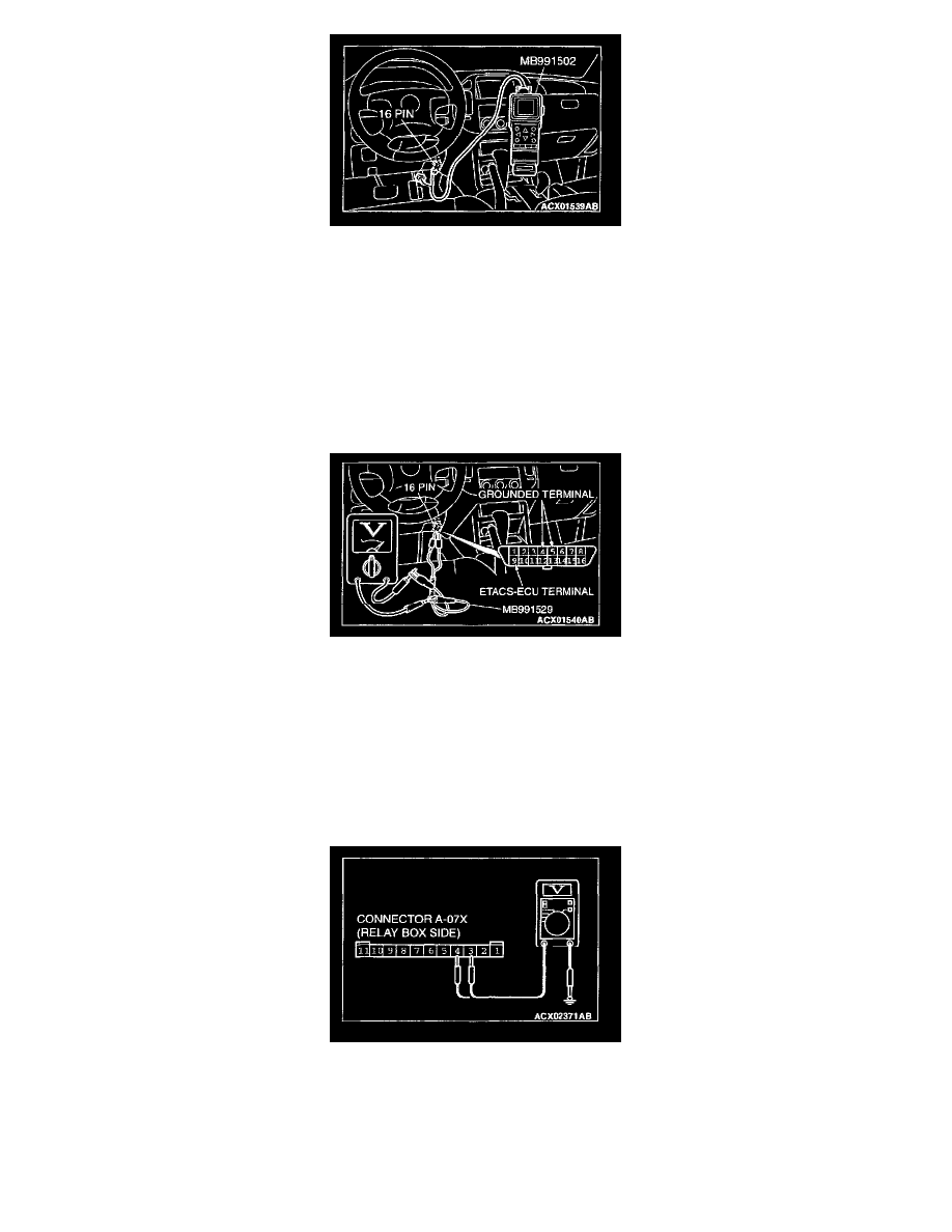
1. Connect scan tool MB991502 to the data link connector.
2. Check that the tone alarm of scan tool MB991502 sounds when the input signal enters.
Q: Does the tone alarm of scan tool MB991502 sound when the input signal enters?
YES: Go to Step 4.
NO: Check the headlight switch input circuit. Refer to Inspection Procedure Q-14.
STEP 3. Check the input signal (by using a voltmeter).
Check the input signal from the headlight switch.
1. Use special tool MB991529 to connect a voltmeter between ground terminal 4 or 5 and ETACS-ECU terminal 9 of the data link connector.
2. Check that the voltmeter indicator deflects once when the input signal enters.
Q: Does the voltmeter indicator deflect?
YES: Go to Step 4.
NO: Check the headlight switch input circuit. Refer to Inspection Procedure Q-14.
STEP 4. Check the front-ECU power supply circuit [for headlight (low-beam)] at the front-ECU connector A-07X.
1. Disconnect the front-ECU connector A-07X and measure at the relay box side.
2. Measure the voltages between terminal 3, 4 and ground.
Q: Is the voltage approximately 12 volts (battery positive voltage)?
YES: Replace the front-ECU. The headlights (low-beam) should illuminate normally.
NO: Go to Step 5.