
Montero XLS 4WD V6-3.5L SOHC (2001)
Check the input signals from the following switches.
-
Ignition switch (IG1)
-
Driver's door switch
-
Taillight switch
-
Headlight switch
CAUTION: To prevent damage to scan tool MB991502, always turn the ignition switch to the "LOCK" (OFF) position before connecting or
disconnecting scan tool MB991502.
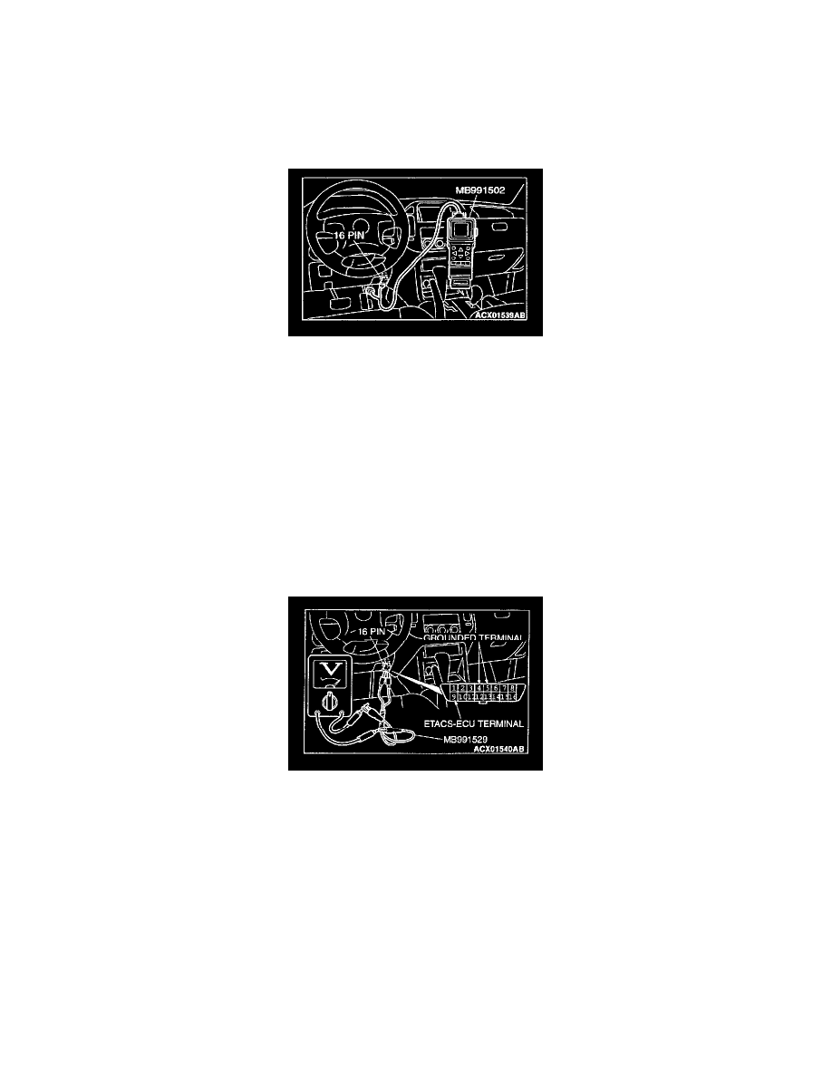
1. Connect scan tool MB991502 to the data link connector.
2. Check that the tone alarm of scan tool MB991502 sounds when the input signal enters.
Q: Does the tone alarm of scan tool MB991502 sound when the input signal enters?
YES: Go to Step 4.
NO: Check the relevant input signal circuit.
STEP 3. Check the input signal (by using a voltmeter).
Check the input signals from the following switches.
-
Ignition switch (IG1)
-
Driver's door switch
-
Taillight switch
-
Headlight switch
1. Use special tool MB991529 to connect a voltmeter between ground terminal 4 or 5 and ETACS-ECU terminal 9 of the data link connector.
2. Check that the voltmeter indicator deflects once when the input signal enters.
Q: Does the voltmeter indicator deflect?
YES: Go to Step 4.
NO: Check the relevant input signal circuit.
STEP 4. Replacement of ECU.
1. Replace the ETACS-ECU.
2. The headlight automatic shutdown function should work normally.
Q: Is the headlight automatic shutdown function working normally?
YES: There is no action to be taken.
NO: Replace the front-ECU. The headlight automatic shutdown function should work normally.