
Montero XLS 4WD V6-3.5L SOHC (2001)
TECHNICAL DESCRIPTION (COMMENT)
The ETACS-ECU arms the theft-alarm system according to the input signals from the following switches:
-
Ignition key reminder switch
-
Driver's and front passenger's door switch
-
Door switches
-
Driver's, front passenger's and back door key cylinder switch
-
Driver's, front passenger's, rear and back door lock actuator switch
-
Hood switch
-
Transmitter
If the theft-alarm system is armed normally, the relevant input signal circuit(s), the theft-alarm indicator light or the ETACS-ECU may be defective.
TROUBLESHOOTING HINTS
-
Malfunction of the theft-alarm indicator light
-
Malfunction of the ignition key reminder switch
-
Malfunction of the driver's or front passenger's door switch
-
Malfunction of the door switches
-
Malfunction of the driver's, front passenger's or back door lock key cylinder switch
-
Malfunction of the driver's, front passenger's, rear or back door lock actuator switch
-
Malfunction of the hood switch
-
Malfunction of the transmitter
-
Malfunction of the ETACS-ECU
-
Damaged harness wires or connectors
DIAGNOSIS
Required Special Tools:
-
MB991223: Test Harness Set
-
MB991502: Scan Tool (MUT-II)
-
MB991529: Diagnostic Trouble Code Check Harness
STEP 1. Check the ETACS-ECU power supply circuit.
Do all of the following functions work when the ignition switch is turned to the "LOCK" (OFF) position?
-
Ignition key reminder tone alarm function
-
Light reminder tone alarm function
-
Central door locking system
-
Hazard warning light
-
Dome light dimming function
Q: Do any of the functions work?
YES: Go to Step 2.
NO: Check the ETACS-ECU battery circuit. Refer to Inspection Procedure R-1.
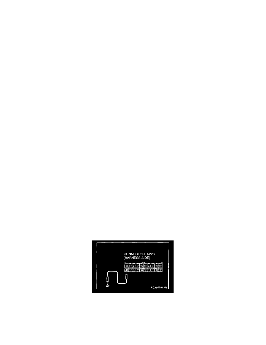
STEP 2. Check the theft-alarm indicator circuit at the ETACS-ECU connector D-223.
1. Disconnect the ETACS-ECU connector D-223 and measure at the harness side.
2. Connect terminal 40 to the ground.
Q: Does the theft-alarm indicator light illuminate?
YES: Go to Step 7 <when using scan tool MB991502> or 8 <when using a voltmeter>.