
Montero XLS 4WD V6-3.5L SOHC (2001)
NOTE: After checking joint connector D-02 and intermediate connector D-28, check the wires. If joint connector D-02 and intermediate connector
D-28 are damaged, repair or replace them. Refer to Harness Connector Inspection.
Q: Are the harness wires between theft-alarm indicator light connector D-104 and fusible link (2) in good condition?
YES: There is no action to be taken.
NO: Repair them. The theft-alarm indicator light should illuminate and the theft-alarm system should be armed normally.
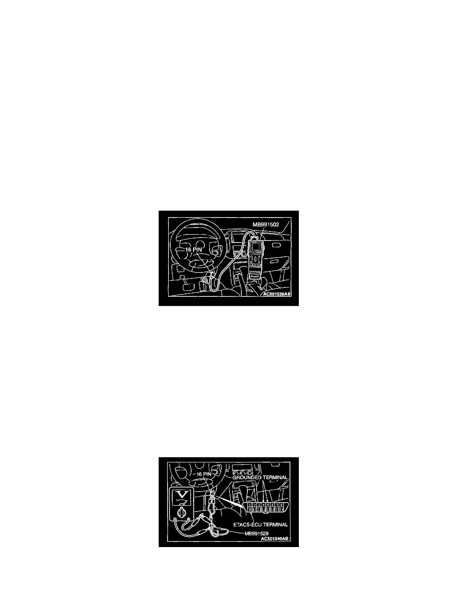
STEP 7. Check the input signal (by using scan tool MB991502).
Check the input signals from the following switches:
-
Ignition key reminder switch
-
Driver's and front passenger's door switch
-
Door switches
-
Driver's, front passenger's and back door lock key cylinder switch
-
Driver's, front passenger's, rear and back door lock actuator switch
-
Hood switch
-
Transmitter
CAUTION: To prevent damage to scan tool MB991502, always turn the ignition switch to the "LOCK" (OFF) position before connecting or
disconnecting scan tool MB991502.
1. Connect scan tool MB991502 to the data link connector.
2. Check that the tone alarm of scan tool MB991502 sounds when the input signal enters.
Q: Does the tone alarm of scan tool MB991502 sound when the input signal enters?
YES: Replace the ETACS-ECU. The theft-alarm indicator light should illuminate, and the theft-alarm system should be armed normally.
NO: Check the relevant input signal circuit.
STEP 8. Check the input signal (by using a voltmeter). Check the input signals from the following switches:
-
Ignition key reminder switch
-
Driver's and front passenger's door switch
-
Door switches
-
Driver's, front passenger's and back door lock key cylinder switch
-
Driver's, front passenger's, rear and back door lock actuator switch
-
Hood switch
-
Transmitter
1. Use special tool MB991529 to connect a voltmeter between ground terminal 4 or 5 and ETACS-ECU terminal 9 of the data link connector.
2. Check that the voltmeter indicator deflects once when the input signal enters.