
Montero XLS 4WD V6-3.5L SOHC (2001)
1. Use special tool MB991529 to connect a voltmeter between ground terminal 4 or 5 and ETACS-ECU terminal 9 of the data link connector.
2. Check that the voltmeter indicator deflects once when the input signal enters.
Q: Does the voltmeter indicator deflect?
YES: Replace the ETACS-ECU. The panic alarm should work normally.
NO: Check the transmitter input signal circuit. Refer to Inspection Procedure Q-17.
Inspection Procedure Q-1
The ignition switch (ACC) signal is not sent to the ETACS-ECU
CIRCUIT OPERATION
The ETACS-ECU operates various functions according to the input signal from the ignition switch (ACC).
TECHNICAL DESCRIPTION (COMMENT)
The ignition switch (ACC) input signal is used to operate the following devices:
-
Windshield wiper and washer
-
Rear wiper and washer
-
Headlight washer
If the signal fails, these devices will not work normally.
TROUBLESHOOTING HINTS
-
Malfunction of the ETACS-ECU
-
Damaged harness wires or connectors
DIAGNOSIS
Required Special Tools:
-
MB991223: Test Harness Set
-
MB991502: Scan Tool (MUT-II)
-
MB991529: Diagnostic Trouble Code Check Harness
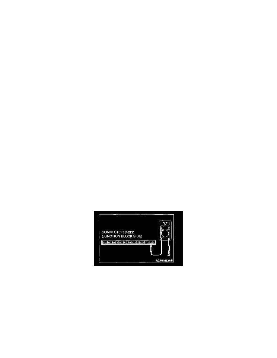
STEP 1. Check the ignition switch (ACC) circuit at the ETACS-ECU connector D-222.
1. Disconnect the ETACS-ECU connector D-222 and measure at the junction block side.
2. Turn the ignition switch to the "ACC" position.
3. Measure the voltage between terminal 2 and ground.
Q: Is the voltage approximately 12 volts (battery positive voltage)?
YES: Replace the ETACS-ECU. The ignition switch (ACC) input signal should be able to be checked and the functions, which are described
in the "Technical Description (comment)," should work normally.
NO: Go to Step 2.