
Montero XLS 4WD V6-3.5L SOHC (2001)
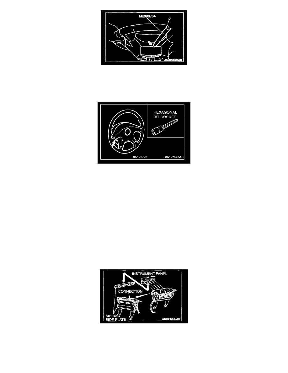
[[B]] Removal of cover
Insert the special tool from the position as shown by the arrow in the illustration to remove the cover.
NOTE: There is a cutout for tool insertion at the inside of position shown in the illustration.
[[C]] Removal of steering wheel air bag module assembly
1. Remove the air bag module and the horn switch connector through the hole appeared after removing the steering wheel cover.
2. Loosen the bolt completely before removing the steering wheel assembly.
NOTE: We recommend to use the commercial hex bit socket or the hexagonal wrench which effective length of hexagonal portion is 75 mm (3.0 in.)
and over and which width across flats is 8 mm (0.3 in.).
Recommended tool: Hex bit socket 8 mm (0.3 in.) (Type: 3010M-160, 4010M-160) made by KOKEN
[[D]] Removal of air bag module (driver's side)
CAUTION:
-
Do not diagnose the circuit using an electric circuit tester or disassemble the air bag module.
-
Keep the removed driver's seat side air bag module at the clean and dry place turning the pad face up.
[[E]] Removal of clock spring
CAUTION: Keep the removed clock spring at the clean and dry place.
[[F]] Removal of air bag side plate
1. After removing the mounting bolt of the air bag side plate, slide the plate downward to disconnect the interfit with the front passenger's side seat
air bag module.
2. After removing the mounting bolts and nuts of the front passenger's side seat air bag module, slide the front passenger's side seat air bag module
crosswise to remove the air bag side plate.