
Pickup 2WD L4-2350cc 2.4L SOHC 8 Valve (1996)
1.
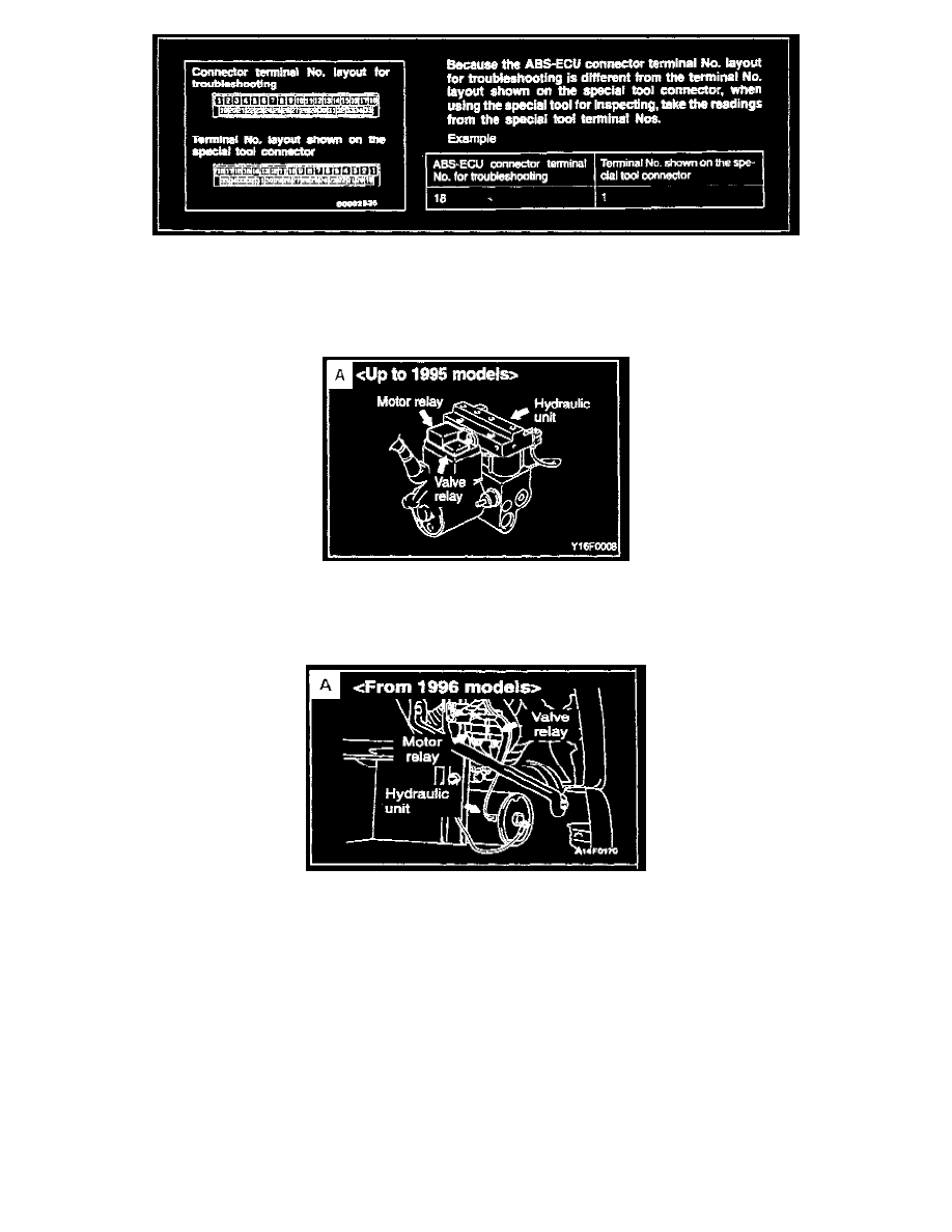
The pin numbers in the ECU connector may appear to be reversed. See Page 35-10 in the 1992-96 Service Manual, Vol. 1 for more information.
Match wire colors to service manual schematics to assist in determining pin numbers.
2.
Most trouble code numbers for 1992-95 models differ from 1996 models. 1992-95 trouble codes are on Page 35-20 in the 1996 3000GT Service
Manual; 1996 trouble codes are on Page 35-51.
3.
MUT-II can be used for all models, but for 1993 and earlier use the adapter harness supplied with the MUT-II.
4.
Early 3000GT hydraulic units may exhibit moisture contamination which usually shows up as a locked up motor, DTC # 52 Motor Relay". The
HU must be replaced.
If the master cylinder is low on fluid, look at the outside of the hydraulic unit and its connections for fluid that would indicate a hydraulic fluid
leak.
5.
The HU used on the 1996 models is smaller than that used on earlier models and is not interchangeable. The same HU is used for both AWD and
FWD on 1996 models.
6.
On early models, if the ABS light comes on intermittently, the cause may be an ABS ECU that reacts too precisely to front or rear wheel sensor
signals. Codes 11, 12, 13, or 14 may be displayed on the scan tool. VR-4 models built after January 1991 and SL models after February 1991 are
equipped with ABS ECU units that are less sensitive to wheel sensor signal variations.
7.
On 1995 and earlier models, the ABS warning light remains lit when the scan tool is connected. On 1996 models, with the scan tool connected, the
ABS light flashes about 10 seconds and then goes off.
8.
The hydraulic control for the rear wheel "select low" function is controlled mechanically on 1992-95 models and electrically on 1996 models.
Diamante
System Type: Sumitomo 3 channel
Diagnostic Page References: 1992-96 Diamante Service Manual, Vol. 1, Pages 35-7 thru 35-43. Circuit diagrams are in Vol. 2, Pages 336 thru 347.
Data Link Connector Location: Under instrument panel, driver side. 1992-96 Diamante Service Manual, Vol. 1, Page 35-12 or Vol. 2, page 346.