
Raider V6-3.7L SOHC (2006)
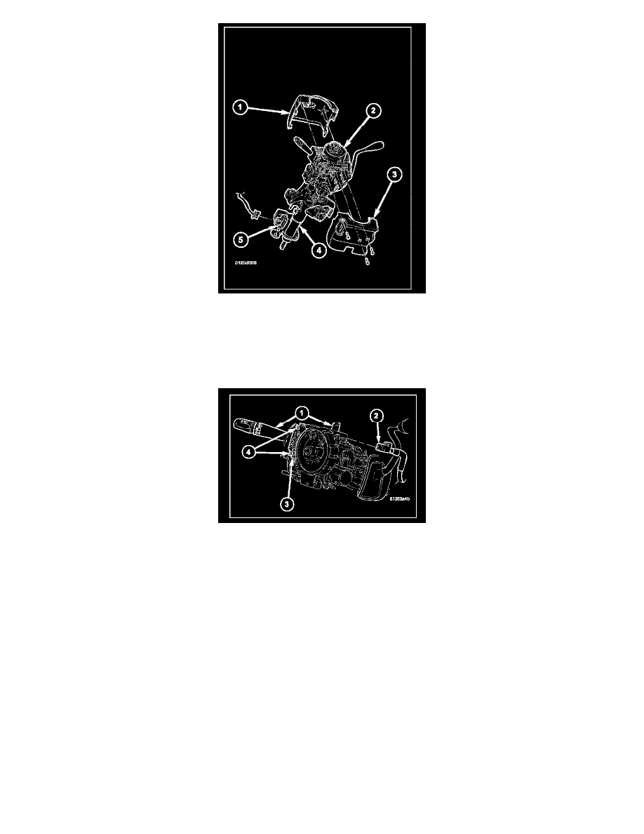
5. Remove the screw (2) that secures the tilt steering column knob (1) and remove it from the tilt actuator (3) on the left side of the column.
6. From below the steering column, remove the two outboard screws that secure the upper column shroud (1) to the lower shroud (3).
7. Using hand pressure, press inward on both sides of the upper shroud above the parting line of the lower shroud to release the snap features that
secure the two shroud halves to each other.
8. Remove the upper shroud from the lower shroud and the steering column.
9. Remove the one center screw that secures the lower shroud to the steering column (4).
10. Remove the lower shroud from the steering column.
11. Disconnect the wire harness connector (2) from the back of the multi-function switch housing (1).
12. Remove the two screws (4) that secure the switch to the multi-function switch mounting housing (3).
13. Grasp the switch control stalk and pull it toward the left side of the vehicle to remove the switch from the mounting housing.
INSTALLATION
WARNING: TO AVOID PERSONAL INJURY OR DEATH, ON VEHICLES EQUIPPED WITH AIRBAGS, DISABLE THE
SUPPLEMENTAL RESTRAINT SYSTEM BEFORE ATTEMPTING ANY STEERING WHEEL, STEERING COLUMN, AIRBAG,
OCCUPANT CLASSIFICATION SYSTEM, SEAT BELT TEN-SIONER, IMPACT SENSOR, OR INSTRUMENT PANEL COMPONENT
DIAGNOSIS OR SERVICE. DISCONNECT AND ISOLATE THE BATTERY NEGATIVE (GROUND) CABLE, THEN WAIT TWO
MINUTES FOR THE SYSTEM CAPACITOR TO DISCHARGE BEFORE PERFORMING FURTHER DIAGNOSIS OR SERVICE. THIS IS
THE ONLY SURE WAY TO DISABLE THE SUPPLEMENTAL RESTRAINT SYSTEM. FAILURE TO TAKE THE PROPER
PRECAUTIONS COULD RESULT IN ACCIDENTAL AIRBAG DEPLOYMENT