
Raider V6-3.7L SOHC (2006)
Combination Switch: Description and Operation
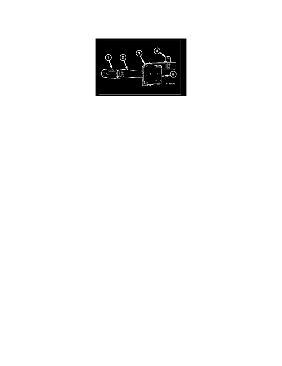
SWITCH - MULTIFUNCTION
DESCRIPTION
The multi-function switch (3) is located on the steering column, just below the steering wheel. The only visible components of the multi-function switch
are the control stalk (2) and control knob (1) that extend through the steering column shrouds on the left side of the column, and the hazard warning push
button (4) that extends through the shroud on the top of the column. The remainder of the switch including its mounting provisions, its electrical
connection, and the turn signal cancel actuator (5) are concealed beneath the shrouds.
The switch housing and controls are constructed of molded black plastic. Each of the switch controls has white International Control and Display Symbol
graphics applied to it, which clearly identify its many functions. Three integral locating posts on the switch housing, one on the top and two on the
bottom, slide into channels in a receptacle on the left side of the multi-function switch mounting housing near the top of the steering column to ensure
proper positioning of the switch. Then two screws secure the switch to the mounting housing. A single integral connector receptacle containing four
terminal pins on the back of the switch housing connects the switch to the vehicle electrical system through a dedicated take out and connector of the
instrument panel wire harness. The multi-function switch provides the vehicle operator with a control interface for the following functions:
-
Hazard Warning Control - The multi-function switch hazard warning push button provides two detent positions (On and Off) to control the
hazard warning lamps.
-
Headlamp Beam Selection - The multi-function switch control stalk provides detent switching for selection of the headlamp high or low beams.
There is also an intermediate momentary position that allows the headlamp high beam circuits to be momentarily flashed to provide an optical
horn feature (sometimes referred to as flash-to-pass) as an optical signalling device.
-
Turn Signal Control - The multi-function switch control stalk provides momentary non-detent (lane change) switching or detent switching with
automatic cancellation for both the left and right turn signal lamps.
-
Washer Control - The multi-function switch control knob provides a momentary position for washer system operation.
-
Wiper Control - The multi-function switch control knob provides two continuous wipe switch positions, low speed or high speed; and, an
intermittent wipe mode with five delay interval positions.
The multi-function switch cannot be adjusted or repaired. If any function of the switch is faulty, or if the switch is damaged, the entire switch must be
replaced as a unit.
OPERATION
The multi-function switch uses resistor multiplexing to control the many functions and features it provides using only three hard wired output circuits.
The switch receives a clean ground from the ElectroMe-chanical Instrument Cluster (EMIC) (also sometimes referred to as the Cab Control Node/CCN)
on a multi-function switch return circuit. It then provides outputs to the EMIC on a wash/beam select switch signal circuit to control washer and
headlamp beam selection, on an intermittent wiper switch signal circuit to control wipers, and on a turn lamps switch signal circuit to control turn signal
and hazard warning functions. The multi-function switch operates as follows:
-
Hazard Warning Control - The hazard warning push button of the multi-function switch is depressed to activate the hazard warning system, and
depressed again to turn the system Off. When the push button is actuated, the multi-function switch provides an output to the EMIC, and the EMIC
responds by sending electronic hazard switch status messages to the Front Control Module (FCM) over the Controller Area Network (CAN) data
bus. The FCM then energizes and flashes or de-energizes both the left and right turn signal circuits to provide the visual hazard warning.
-
Headlamp Beam Selection - The control stalk of the multi-function switch is pulled towards the steering wheel past a detent to actuate the
integral beam select switch circuitry, or to an intermediate, momentary position before the detent to actuate the optical horn feature. Each time the
control stalk is actuated to a detent position, the opposite headlamp beam from what is currently selected will be energized. Each time the control
stalk is actuated to the momentary position with the headlamps turned off, the headlamp high beams will be illuminated for as long as the control
stalk is held in this position. The multi-function switch provides an output to the EMIC, and the EMIC responds by sending electronic beam select
switch status messages to the FCM over the CAN data bus. The FCM energizes or de-energizes the selected low or high beam circuits.
-
Turn Signal Control - The control stalk of the multi-function switch is moved upward to activate the right turn signal circuitry, and, downward to
activate the left turn signal circuitry. The turn signal switch has a detent position in each direction that provides turn signals with automatic
cancellation, and an intermediate, momentary position in each direction that provides turn signals only until the control stalk is released. When the
control stalk is moved to a detent turn signal switch position, the cancel actuator extends toward the center of the steering column. A turn signal
cancel cam that is integral to the clockspring rotates with the steering wheel and the cam lobes contact the cancel actuator when it is extended from
the multi-function switch. When the steering wheel is rotated during a turning maneuver, one of the two turn signal cancel cam lobes will contact
the turn signal cancel actuator. The cancel actuator latches against the cancel cam rotation in the direction opposite that which is signaled. If the