
Raider V6-3.7L SOHC (2006)
Turn Signal Cancel Cam: Description and Operation
CAM - TURN SIGNAL CANCEL
DESCRIPTION
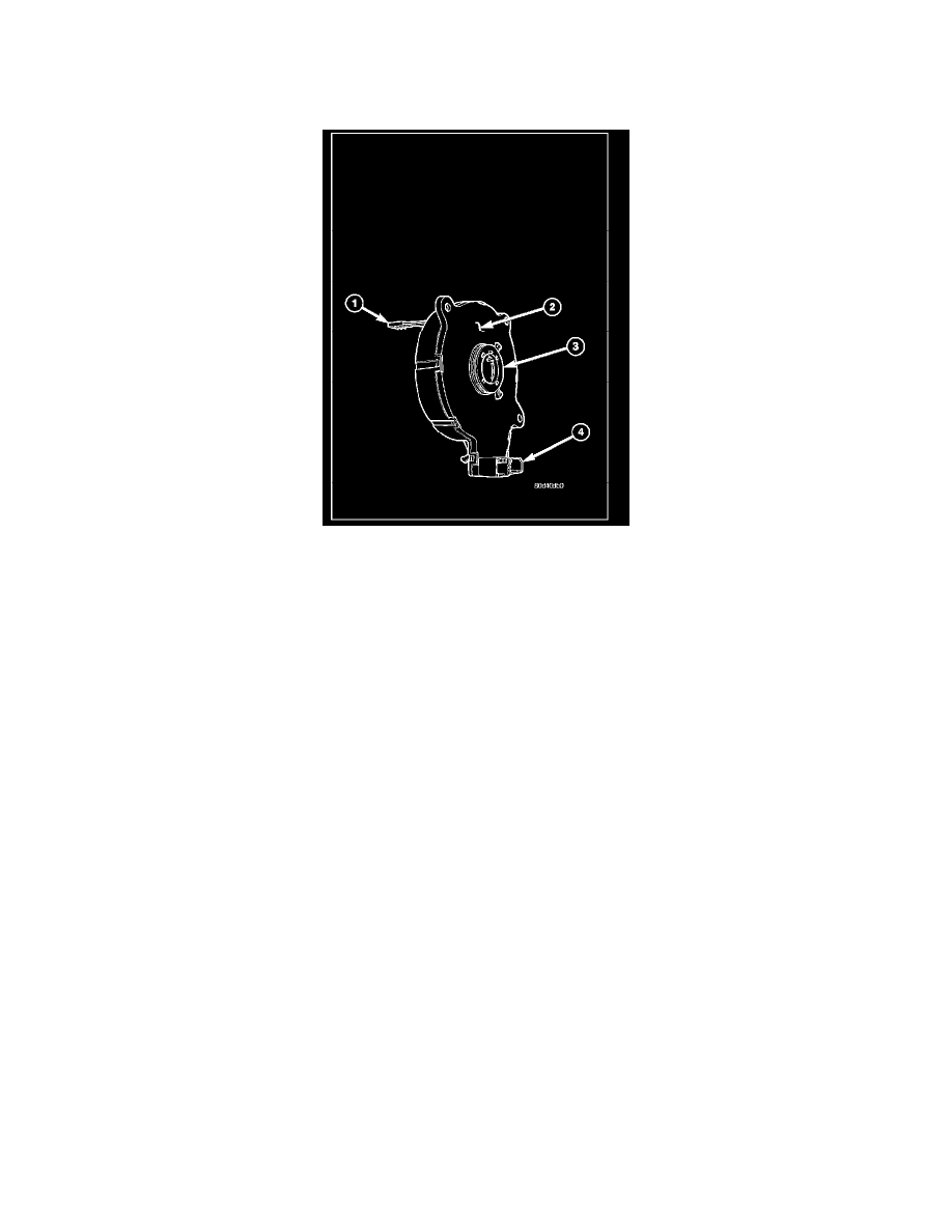
The turn signal cancel cam (3) is concealed within the steering column. The turn signal cancel cam consists of two lobes on a molded plastic ring that is
snapped into the lower hub of the clockspring rotor. The clockspring mechanism provides turn signal cancellation as well as a constant electrical
connection between the horn switch, driver airbag, speed control switches, and remote radio switches on the steering wheel and the instrument panel wire
harness on the steering column. The housing of the clockspring (2) is secured to the multi-function switch mounting housing on the steering column and
remains stationary. The rotor of the clockspring, including the turn signal cancel cam lobes rotate with the steering wheel.
The turn signal cancel cam is serviced as a unit with the clockspring and cannot be repaired. If faulty or damaged, the entire clockspring unit must be
replaced.
OPERATION
When the multi-function switch control stalk is moved to a latched turn signal position, a turn signal cancel actuator is extended from the inside surface
of the switch housing toward the turn signal cancel cam. As the steering wheel is rotated to complete the turn, one of the two cam lobes will contact the
actuator, automatically cancelling the turn signal event and releasing the latched multi-function switch control stalk to the neutral position.