
Raider V6-3.7L SOHC (2006)
Pressure Regulating Solenoid: Description and Operation
Automatic Transmission - 545RFE
Switch Valve - Solenoid
SWITCH VALVE - SOLENOID
DESCRIPTION
The Solenoid Switch Valve (SSV) is located in the valve body and controls the direction of the transmission fluid when the L/R-TCC solenoid is
energized.
OPERATION
The Solenoid Switch Valve controls line pressure from the LR-TCC solenoid. In 1st gear, the SSV will be in the downshifted position, thus directing
fluid to the L/R clutch circuit. In 2nd, 3rd, 4th, and 5th gears, the solenoid switch valve will be in the upshifted position and directs the fluid into the
torque converter clutch (TCC) circuit.
When shifting into 1st gear, a special hydraulic sequence is performed to ensure SSV movement into the downshifted position. The L/R pressure
switch is monitored to confirm SSV movement. If the movement is not confirmed (the L/R pressure switch does not close), 2nd gear is substituted for
1st. A DTC will be set after three unsuccessful attempts are made to get into 1st gear in one given key start.
Assembly - Transmission Solenoid/TRS
ASSEMBLY - TRANSMISSION SOLENOID/TRS
DESCRIPTION
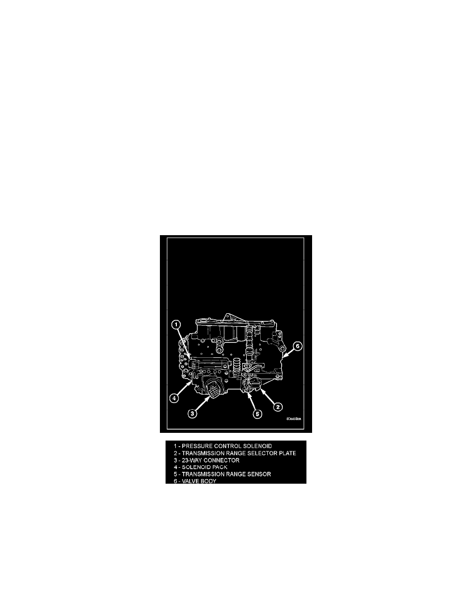
The transmission solenoid/TRS assembly is internal to the transmission and mounted on the valve body assembly. The assembly consists of six
solenoids that control hydraulic pressure to the six friction elements (transmission clutches), and the torque converter clutch. The pressure control
solenoid is located on the side of the solenoid/TRS assembly. The solenoid/TRS assembly also contains five pressure switches that feed information to
the TCM.
OPERATION SOLENOIDS
Solenoids are used to control the L/R, 2C, 4C, OD, and UD friction elements. The reverse clutch is controlled by line pressure and the position of the
manual valve in the valve body. All the solenoids are contained within the Solenoid and Pressure Switch Assembly. The solenoid and pressure switch
assembly contains one additional solenoid, Multi-Select (MS), which serves primarily to provide 2nd and 3rd gear limp-in operation. The solenoids
receive electrical power from the Transmission Control Relay through a single wire. The TCM energizes or operates the solenoids individually by
grounding the return wire of the solenoid as necessary. When a solenoid is energized, the solenoid valve shifts, and a fluid passage is opened or closed