
Raider V6-3.7L SOHC (2006)
Wiper Control Module: Description and Operation
WIPER MODULE
DESCRIPTION
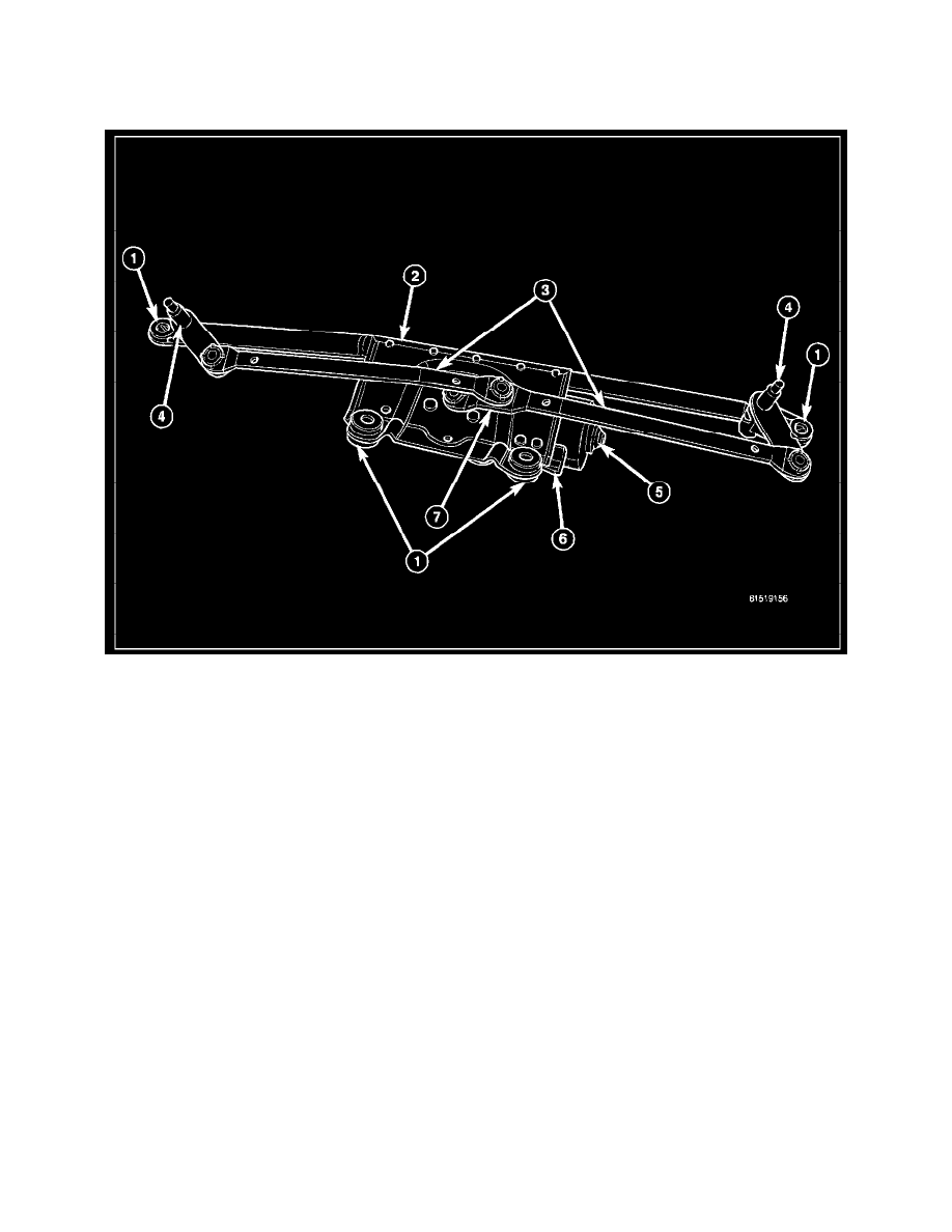
The wiper module is secured with screws through four rubber grommet-type insulators (1) to the cowl plenum panel. The module is concealed beneath
the molded plastic cowl plenum cover/grille panel between the base of the windshield and the rear edge of the hood panel. The ends of the pivot shafts
protruding through openings in the cowl plenum cover/grille panel to drive the wiper arms and blades are the only visible components of the wiper
module. The wiper module consists of the following major components:
-
Bracket - The wiper module bracket (2) consists of a long tubular steel main member that has a die cast pivot bracket at each end to which the two
wiper pivots (4) are secured. A stamped steel motor bracket is welded near the center of the tubular member to which the wiper motor (5) is
secured.
-
Crank Arm (7) - The wiper motor crank arm is a stamped steel unit with a slotted hole on the driven end that is secured to the wiper motor output
shaft with a nut, and has a ball stud secured to the drive end.
-
Linkage (3) - Two stamped steel drive links connect the wiper motor crank arm to the wiper pivot lever arms. The right side drive link has a
plastic socket-type bushing on each end. The left side drive link has a plastic socket-type bushing on one end, and a plastic sleeve-type bushing on
the other end. The socket-type bushing on one end of each drive link is snap-fit over the ball stud on the lever arm of its respective pivot. The left
side drive link sleeve-type bushing end is then fit over the motor crank arm ball stud, and the other socket-type bushing of the right side drive link
is snap-fit over the exposed end of the wiper motor crank arm ball stud.
-
Motor (5) - The wiper motor features a transmission housing from which the wiper motor output shaft exits and three threaded holes that mount
the motor to the module bracket with three screws. A nut secures the wiper motor crank arm to the motor output shaft. The two-speed permanent
magnet wiper motor features an integral transmission, an internal park switch, and an internal automatic resetting circuit breaker. A short pigtail
wire and connector (6) connect the wiper motor to the vehicle electrical system through a dedicated take out and connector of the headlamp and
dash wire harness.
-
Pivots (4) - The two wiper pivots are secured within the die cast pivot brackets on the outboard ends of the wiper module main member. The lever
arms that extend from the center of the pivot shafts each have a ball stud on their end. The upper end of each pivot shaft where the wiper arms will
be fastened each has a serrated driver with a threaded stud. The lower ends of the pivot shafts are installed through lubricated bushings in the pivot
brackets and are secured with snap rings.