
Raider V6-3.7L SOHC (2006)
Headlamp Switch: Description and Operation
SWITCH - HEADLAMP
DESCRIPTION
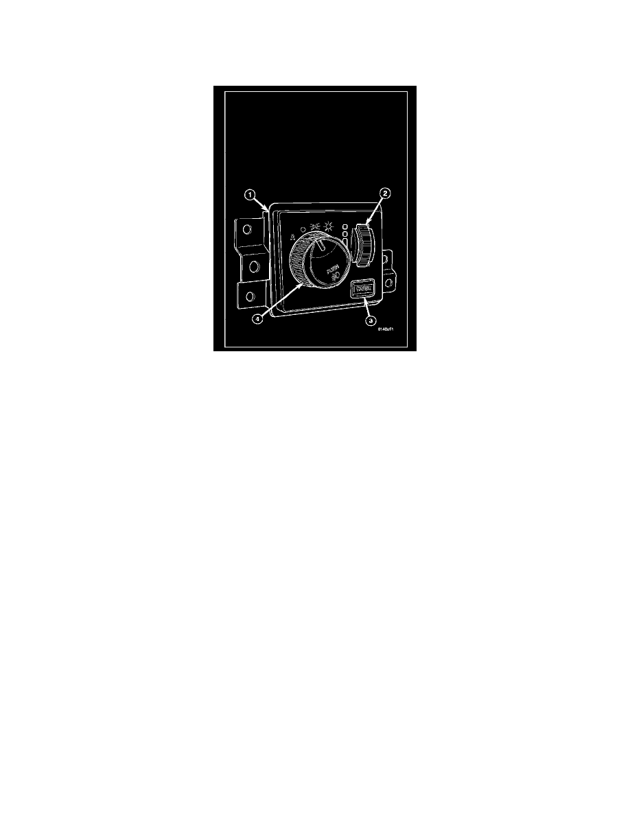
The headlamp switch (1) is located on the instrument panel, to the left of the steering column. Three different switches are used. The standard switch
features a three detent position rotary knob (4) for exterior lighting control, a thumb wheel (2) for panel lamps dimming and interior lighting control, and
a momentary push button (3) for cargo lamp control. An optional switch has a momentary "Push" function added to the rotary knob for front fog lamp
control. A second optional switch has the same thumb wheel and momentary push button, but has a fourth detent position added to the rotary knob for
selecting the optional automatic headlamps feature. Each of these switches is constructed of molded plastic. The rotary knob is molded plastic and
knurled around its circumference to ease operator control. On models with optional fog lamps the rotary knob also has the text "PUSH" and an
International Control and Display Symbol icon for "Front Fog Light" applied to it. The thumb wheel is also plastic and knurled. The cargo lamp push
button is plastic with a smooth finish and the text "CARGO" applied to it. The switch face plate is also labeled with graphics and icons to clearly identify
the many functions of the rotary knob and thumb wheel. Three screws secure the switch to the back of the cluster bezel through integral mounting flanges
that are molded to each side of the switch housing. The back of the switch housing has an integral connector receptacle containing terminal pins that
connect the switch to the vehicle electrical system through a dedicated take out and connector of the instrument panel wire harness. A panel dimmer
controlled incandescent bulb soldered to the circuit board within the switch provides back lighting for visibility at night, but is not serviceable. The
headlamp switch cannot be repaired and, if faulty or damaged, it must be replaced.
OPERATION
The headlamp switch uses two resistor multiplexed outputs and one conventional output to control the many functions and features it provides. The
switch receives a clean ground from the Electro Mechanical Instrument Cluster (EMIC) (also sometimes referred to as the Cab Control Node/CCN) on a
headlamp switch return circuit. It then provides outputs to the EMIC on a headlamp switch signal circuit to control exterior lighting functions, on a panel
lamps dimmer signal circuit to control panel dimmer and interior lighting functions, and on a cargo lamp return circuit to control the cargo lamps.
The switch illumination circuit receives a path to ground at all times through the left instrument panel ground circuit. The illumination level is controlled
by a Pulse-Width Modulated (PWM) output received from the EMIC on a headlamp switch illumination control circuit. The EMIC controls this output
based upon the dimmer signal select mux input from the headlamp switch. The headlamp switch operates as follows:
-
Cargo Lamps Control - The cargo lamp push button on the headlamp switch is depressed to activate or deactivate the cargo lamps. The
headlamp switch provides an output to the EMIC, and the EMIC responds by providing the appropriate cargo lighting control outputs through its
internal cargo lamp driver circuit.
-
Front Fog Lamps Control - For vehicles so equipped, the rotary knob on the headlamp switch is depressed to activate or deactivate the optional
front fog lamps. The headlamp switch provides an output to the EMIC, and the EMIC responds by sending electronic fog lamp switch status
messages to the Front Control Module (FCM) over the Controller Area Network (CAN) data bus. The FCM responds by energizing or
de-energizing the front fog lamp relay in the Power Distribution Center (PDC) and by sending an electronic message back to the EMIC to control
the front fog lamp indicator.
-
Exterior Lighting Control - The rotary knob on the headlamp switch is rotated to a detent position to activate or deactivate the exterior lighting.
The headlamp switch provides an output to the EMIC, and the EMIC responds by sending electronic exterior lighting switch status messages to the
FCM over the CAN data bus. The FCM responds by energizing or de-energizing the park lamp relay in the PDC and the high or low beam
headlamp circuits, and by sending an electronic message back to the EMIC to control the high beam indicator. The FCM also remembers which