
Raider V6-3.7L SOHC (2006)
(vented or applied), depending on its default operating state. The result is an apply or release of a frictional element. The MS and UD solenoids are
normally applied to allow transmission limp-in in the event of an electrical failure. The continuity of the solenoids and circuits are periodically tested.
Each solenoid is turned on or off depending on its current state. An inductive spike should be detected by the TCM during this test. If no spike is
detected, the circuit is tested again to verify the failure. In addition to the periodic testing, the solenoid circuits are tested if a speed ratio or pressure
switch error occurs.
PRESSURE SWITCHES
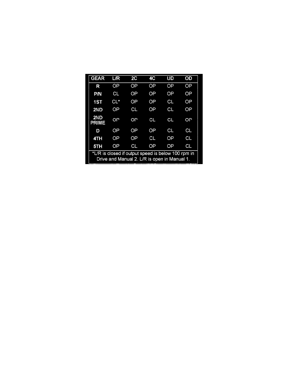
The TCM relies on five pressure switches to monitor fluid pressure in the L/R, 2C, 4C, UD, and OD hydraulic circuits. The primary purpose of these
switches is to help the TCM detect when clutch circuit hydraulic failures occur. The switches close at approximately 23 psi and open at approximately
11 psi, and simply indicate whether or not pressure exists. The switches are continuously monitored by the TCM for the correct states (open or closed)
in each gear as shown in the following chart:
A Diagnostic Trouble Code (DTC) will set if the TCM senses any switch open or closed at the wrong time in a given gear.