
Raider V6-3.7L SOHC (2006)
1. Raise and support vehicle.
2. Clean all foreign material from the propeller shaft and universal joints.
3. Inspect propeller shaft for missing balance weights, broken welds and bent areas. If propeller shaft is bent, it must be replaced.
4. Inspect universal joints for wear and properly installed.
5. Check propeller shaft bolt torques.
6. Remove wheels and install lug nuts to retain brake rotors.
7. Mark and number the shaft six inches from the pinion yoke end at four positions 90° apart.
8. Run and accelerate vehicle until vibration occurs. Note the intensity and speed the vibration occurred. Stop the engine.
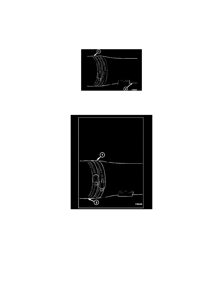
9. Install a screw clamp at position (1).
10. Start engine and check vibration. If there is little or no change move the clamp to the next positions. Repeat the vibration test.
NOTE: If there is no difference in vibration at this positions, the vibration may not be the propeller shaft.
11. If vibration decreased, install a second clamp (1) and repeat the test.
12. If additional clamp causes an additional vibration, separate the clamps 1/2 inch (1) above and below the mark. Repeat the vibration test.
13. Increase distance between the clamp screws (1) (2) and repeat test, until the least amount of vibration is noticed. Bend the slack end of the clamps
so screws will not loosen.
14. If vibration remains unacceptable, repeat the procedure to the front end of the propeller shaft.
15. Install wheels and lower vehicle.
PROPELLER SHAFT RUNOUT
1. Clean propeller shaft surface, where dial indicator will contact the shaft.
2. Install dial indicator perpendicular to the shaft surface.
3. Measure runout at the center and ends of the shaft away from weld areas, so weld process does not affect measurements.
4. Refer to Runout Specifications chart.
5. If runout is out of specification, index the shaft 180° and take shaft runout measurements again.
6. If runout is now within specifications, mark shaft and yokes for proper orientation.
7. If runout is not within specifications, verify runout of the transmission/transfer case and axle are within specifications. Correct as necessary and
measure propeller shaft runout again.