
Raider V6-3.7L SOHC (2006)
Four Wheel Drive Selector Switch: Description and Operation
Transfer Case - NV233 - A/T
SWITCH - TRANSFER CASE SELECTOR
DESCRIPTION
The selector switch assembly is mounted in the right side of the vehicle's Instrument Panel (IP) and consists of a rotary knob connected to a resistive
network for the mode and range shift selections. Also located in this assembly is a recessed, normally open momentary switch for making shifts into
and out of transfer case NEUTRAL. A pen, or similar instrument, is used to make a NEUTRAL shift selection, thus reducing the likelihood of an
inadvertent shift request.
OPERATION
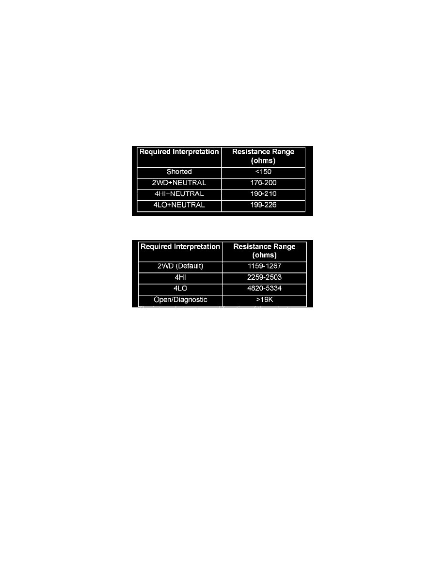
As the position of the selector switch varies, the resistance between the Mode Sensor supply voltage pin and the Mode Sensor output will vary.
Hardware, software, and calibrations within the Front Control Module (FCM) are provided that interpret the selector switch resistance as given in the
table below: SELECTOR SWITCH INTERPRETATION
SELECTOR SWITCH INTERPRETATION
SELECTOR SWITCH INTERPRETATION
The internal structure and-function of the selector switch is such that the connection is made to the Open/Diagnostic resistor before the connection to
the individual position resistors is broken. Because of this characteristic, if the resistance between the Mode Sensor supply voltage pin and the Mode
Sensor output pin is >19k ohms, the position resistor is open.