
Raider 2WD V6-3.7L (2008)
10. Repeat the Plastigage measurement to verify your bearing selection prior to final assembly.
11. Once you have selected the proper insert, install the insert and cap. Tighten the connecting rod bolts to 27 Nm (20 ft. lbs.) plus a 90° turn.
Slide snug-fitting feeler gauge between the connecting rod and crankshaft journal flange. Refer to Engine Specifications for the proper clearance.
Replace the connecting rod if the side clearance is not within specification.
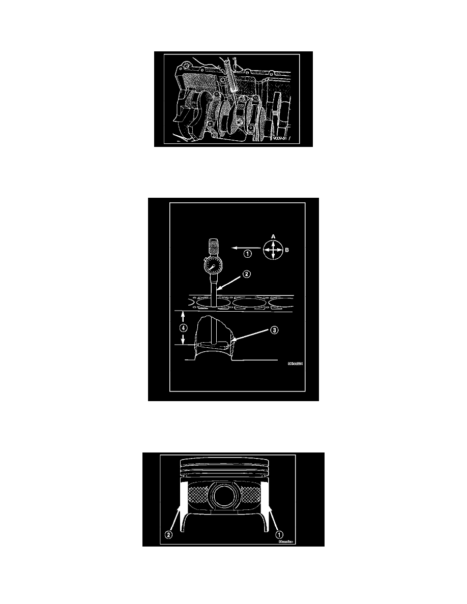
PISTON FITTING
1. To correctly select the proper size piston, a cylinder bore gauge (2), capable of reading in 0.003 mm (0.0001 in.) INCREMENTS is required. If a
bore gauge is not available, do not use an inside micrometer.
2. Measure the inside diameter of the cylinder bore at a point 38.0 mm (1.5 inches) below top of bore (4). Start perpendicular (across or at 90°) to the
axis of the crankshaft at point A and then take an additional bore reading 90° to that at point B.
3. The coated pistons will be serviced with the piston pin and connecting rod pre-assembled.
4. The coating material (1) and (2) is applied to the piston after the final piston machining process. Measuring the outside diameter of a coated piston
will not provide accurate results. Therefore measuring the inside diameter of the cylinder bore with a dial Bore Gauge is MANDATORY. To