
Raider 2WD V6-3.7L (2008)
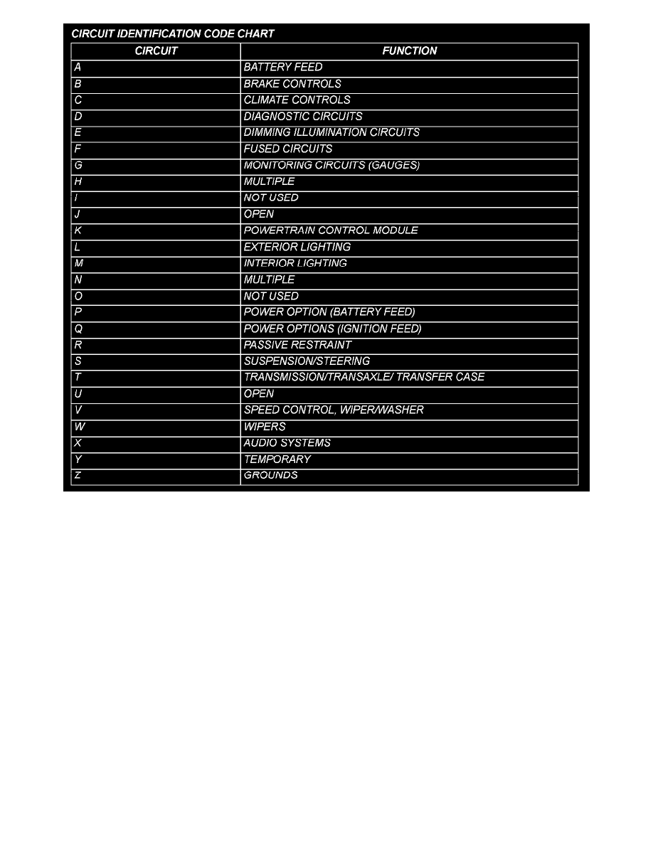
All circuits in the diagrams use an alpha/numeric code to identify the wire and it's function. To identify which circuit code applies to a system, refer to
the Circuit Identification Code Chart. This chart shows the main circuits only and does not show the secondary codes that may apply to some models.
SECTION IDENTIFICATION AND INFORMATION
The wiring diagrams are grouped into individual sections. If a component is most likely found in a particular group, it will be shown complete (all wires,
connectors, and pins) within that group.
In the Splice Information section, splice diagrams show the entire splice and provide references to other sections the splices serves. It only contains
splice diagrams that are not shown in their entirety somewhere else in the wiring diagrams.
Each connector and the circuits involved with that connector are shown. The connectors are identified using the name/number on the diagram pages.
CONNECTOR, GROUND AND SPLICE INFORMATION
CAUTION: Not all connectors are serviced. Some connectors are serviced only with a harness. A typical example might be the Supplemental
Restraint System connectors. Always check parts availability before attempting a repair.
IDENTIFICATION
In-line connectors are identified by a number, as follows:
-
In-line connectors located in the engine compartment are C100 series numbers.
-
In-line connectors located in the instrument panel area are C200 series numbers.
-
In-line connectors located in the body are C300 series numbers.
-
Jumper harness connectors are C400 series numbers.
-
Grounds and ground connectors are identified with a "G" and follow the same series numbering as the in-line connectors.