
Raider 2WD V6-3.7L (2008)
Control Assembly: Service and Repair
Illumination Lamp
ILLUMINATION LAMP
BULB-A/C-HEAT CONTROL REMOVAL
WARNING: To avoid serious or fatal injury on vehicles equipped with airbags, disable the Supplemental Restraint System (SRS) before
attempting any steering wheel, steering column, airbag, seat belt tensioner, impact sensor, or instrument panel component diagnosis or service.
Disconnect and isolate the battery negative (ground) cable, then wait two minutes for the system capacitor to discharge before performing
further diagnosis or service. This is the only sure way to disable the SRS. Failure to take the proper precautions could result in accidental
airbag deployment.
NOTE: There may be minor variations in the locations of the bulb/bulb holder units on the back of the A/C-heater control as a result of various optional
A/C-heater control units. However, the bulb types and service procedures are identical for all of these bulbs.
1. Disconnect and isolate the battery negative cable.
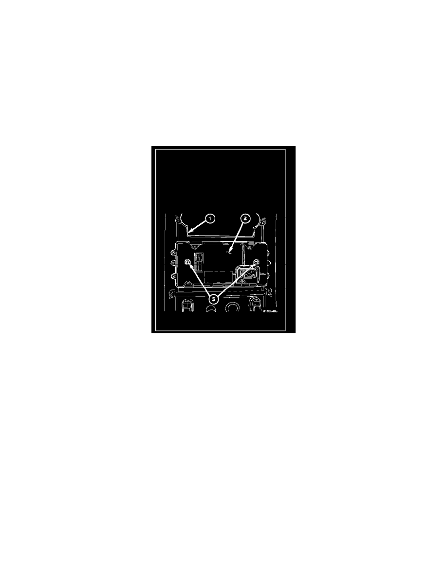
2. Remove the center bezel (1) from the instrument panel.
3. Use a small thin-bladed screwdriver to rotate the bulb holder (3) counterclockwise about 30 degrees to unlock it from the keyed opening in the
front A/C-heater control (2) circuit board.
4. Pull the bulb holder and bulb straight out of the circuit board.
ILLUMINATION LAMP-BULB-CMTC CONTROL REMOVAL
WARNING: To avoid serious or fatal injury on vehicles equipped with airbags, disable the Supplemental Restraint System (SRS) before
attempting any steering wheel, steering column, airbag, seat belt tensioner, impact sensor, or instrument panel component diagnosis or service.
Disconnect and isolate the battery negative (ground) cable, then wait two minutes for the system capacitor to discharge before performing
further diagnosis or service. This is the only sure way to disable the SRS. Failure to take the proper precautions could result in accidental
airbag deployment.
NOTE: There are provisions for up to four bulb/bulb holder units on the Compass Mini-Trip Computer (CMTC) circuit board. The two outboard bulbs
illuminate the CMTC push buttons, while the two center bulbs illuminate the optional universal transmitter push buttons. Therefore, the center bulb
locations are only populated on vehicles equipped with the optional universal transmitter.