
Raider 2WD V6-3.7L (2008)
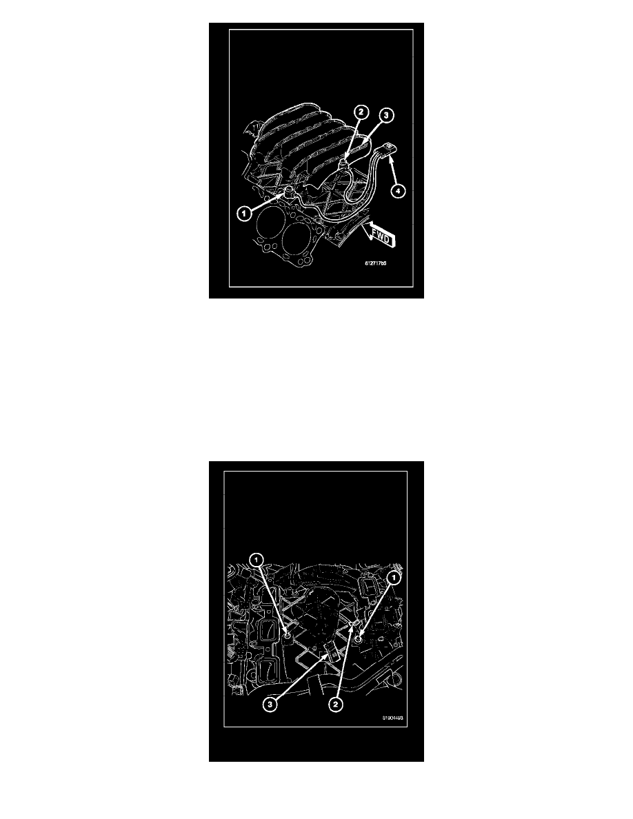
The two knock sensors (1) are bolted into the cylinder block under the intake manifold (3).
NOTE: The left sensor is identified by an identification tag (LEFT). It is also identified by a larger bolt head. The Powertrain Control Module (PCM)
must have and know the correct sensor left/right positions. Do not mix the sensor locations.
1. Disconnect knock sensor dual pigtail harness from engine wiring harness. This connection is made near rear of engine.
2. Remove intake manifold. Refer to Engine section.
3. Remove sensor mounting bolts (2). Note foam strip on bolt threads. This foam is used only to retain the bolts to sensors for plant assembly. It is
not used as a sealant. Do not apply any adhesive, sealant or thread locking compound to these bolts.
4. Remove sensors from engine.
INSTALLATION [3.7L]
NOTE: The left sensor is identified by an identification tag (LEFT) (2). It is also identified by a larger bolt head. The Powertrain Control Module