
Raider 2WD V6-3.7L (2008)
Air Bag Control Module: Description and Operation
MODULE - OCCUPANT RESTRAINT CONTROLLER
DESCRIPTION
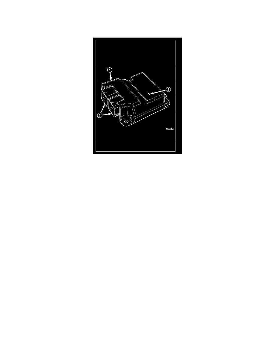
The Occupant Restraint Controller (ORC) (1) is located below the instrument panel center stack in the passenger compartment of the vehicle, where it is
secured by three nuts to three studs on a stamped steel mounting bracket welded onto the top of the floor panel transmission tunnel just forward of the
instrument panel center support bracket. Concealed within a hollow in the center of the die cast aluminum ORC housing is the electronic circuitry of the
ORC which includes a microprocessor, an electronic impact sensor, an electronic safing sensor, and an energy storage capacitor. A stamped metal cover
plate is secured to the bottom of the ORC housing with screws to enclose and protect the internal electronic circuitry and components.
An arrow (2) printed on the label on the top of the ORC housing provides a visual verification of the proper orientation of the unit, and should always be
pointed toward the front of the vehicle. The ORC housing has three integral flanges with mounting holes. Two are on the corners oriented towards the
rear of the vehicle, and one is near the center of the side facing the front of the vehicle. A molded plastic electrical connector (3) with two receptacles,
each containing up to 32 terminal pins, exits the left facing side of the ORC housing. These terminal pins connect the ORC to the vehicle electrical
system through two dedicated take outs and connectors, one each from the instrument panel and the body wire harnesses.
The impact sensor and safing sensor internal to the ORC are calibrated for the specific vehicle, and are only serviced as a unit with the ORC. In addition,
there are unique versions of the ORC for vehicles with or without the optional side curtain airbags. The ORC cannot be repaired or adjusted and, if
damaged or ineffective, it must be replaced.
OPERATION
The microprocessor in the Occupant Restraint Controller (ORC) contains the Supplemental Restraint System (SRS) logic circuits and controls all of the
SRS components. The ORC uses On-Board Diagnostics (OBD) and can communicate with other electronic modules in the vehicle as well as with the
diagnostic scan tool using the Controller Area Network (CAN) data bus. This method of communication is used for control of the airbag indicator in the
ElectroMechanical Instrument Cluster (EMIC) (also known as the Cab Compartment Node/CCN) and for SRS diagnosis and testing through the 16-way
data link connector located on the driver side lower edge of the instrument panel.
The ORC microprocessor continuously monitors all of the SRS electrical circuits to determine the system readiness. If the ORC detects a monitored
system fault, it sets an active and stored Diagnostic Trouble Code (DTC) and sends electronic messages to the EMIC over the CAN data bus to turn ON
the airbag indicator. An active fault only remains for the duration of the fault, or in some cases for the duration of the current ignition switch cycle, while
a stored fault causes a DTC to be stored in memory by the ORC. For some DTCs, if a fault does not recur for a number of ignition cycles, the ORC will
automatically erase the stored DTC. For other internal faults, the stored DTC is latched forever.
The ORC receives battery current through two circuits; a fused ignition switch output (run) circuit through a fuse in the Junction Block (JB), and a fused
ignition switch output (run-start) circuit through a second fuse in the JB. The ORC receives ground through a ground circuit and take out of the
instrument panel wire harness. This take out has a single eyelet terminal connector that is secured by a ground screw to the left side of the floor panel
transmission tunnel near the center of the instrument panel center support. These connections allow the ORC to be operational whenever the ignition
switch is in the START or ON positions.