
Raider 2WD V6-3.7L SOHC (2007)
Alarm Module: Description and Operation
VEHICLE THEFT SECURITY - SERVICE INFORMATION
SENTRY KEY IMMOBILIZER SYSTEM
Sentry Key Immobilizer System
The Sentry Key Immobilizer System (SKIS) is available as a factory-installed option on this vehicle. Vehicles equipped with this option can be readily
identified by the illumination of the security indicator in the instrument cluster for about three seconds after the ignition switch is turned to the ON
position as a SKIS bulb test.
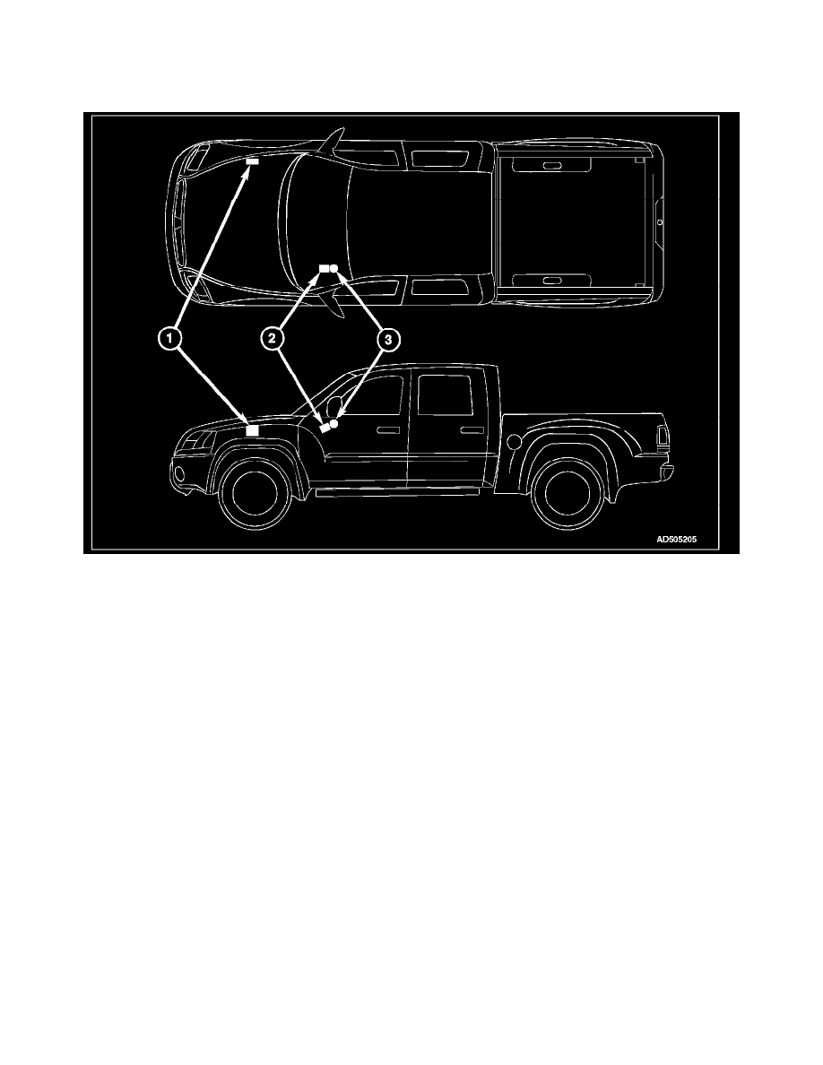
The SKIS includes the following major components, which are described in further detail elsewhere in this service information:
-
Powertrain Control Module (1) - The Powertrain Control Module (PCM) is located in the engine compartment and provides the SKIS engine
control logic.
-
Security Indicator - A security indicator is integral to the Electromechanical Instrument Cluster (EMIC) (also known as the Cab Compartment
Node/CCN).
-
Sentry Key Remote Entry Module (2) - The Sentry Key REmote Entry Module (SKREEM) (also known as the Wireless Control Module/
WCM) is located on the right side of the steering column near the ignition lock cylinder housing and an integral molded plastic antenna ring circles
the ignition lock cylinder like a halo. The SKREEM and its antenna are concealed beneath the steering column shrouds. Two SKREEM modules
are available: one for vehicles equipped with Remote Keyless Entry (RKE) only, and one for vehicles equipped with RKE and SKIS.
-
Sentry Key Transponder (3) - The Sentry Key transponder is contained within the Remote Keyless Entry (RKE) transmitter on the ignition key.
Except for the Sentry Key transponders, which rely upon Radio Frequency (RF) communication, hard wired circuitry connects the SKIS components to
the electrical system of the vehicle. These hard wired circuits are integral to several wire harnesses, which are routed throughout the vehicle and retained
by many different methods. These circuits may be connected to each other, to the vehicle electrical system and to the SKIS components through the use
of a combination of soldered splices, splice block connectors, and many different types of wire harness terminal connectors and insulators. Refer to the
appropriate wiring information. The wiring information includes wiring diagrams, proper wire and connector repair procedures, further details on wire
harness routing and retention, as well as pin-out and location views for the various wire harness connectors, splices and grounds.
VEHICLE THEFT SECURITY SYSTEM