
Raider 4WD V6-3.7L SOHC (2007)
Brake Light Switch: Service and Repair
REMOVAL
WARNING: To avoid personal injury or death, on vehicles equipped with airbags, disable the supplemental restraint system before attempting
any steering wheel, steering column, airbag, seat belt tensioner, impact sensor, or instrument panel component diagnosis or service. Disconnect
and isolate the battery negative (ground) cable, then wait two minutes for the system capacitor to discharge before performing further
diagnosis or service. This is the only sure way to disable the supplemental restraint system. Failure to take the proper precautions could result
in accidental airbag deployment.
1. Disconnect and isolate the battery negative cable.
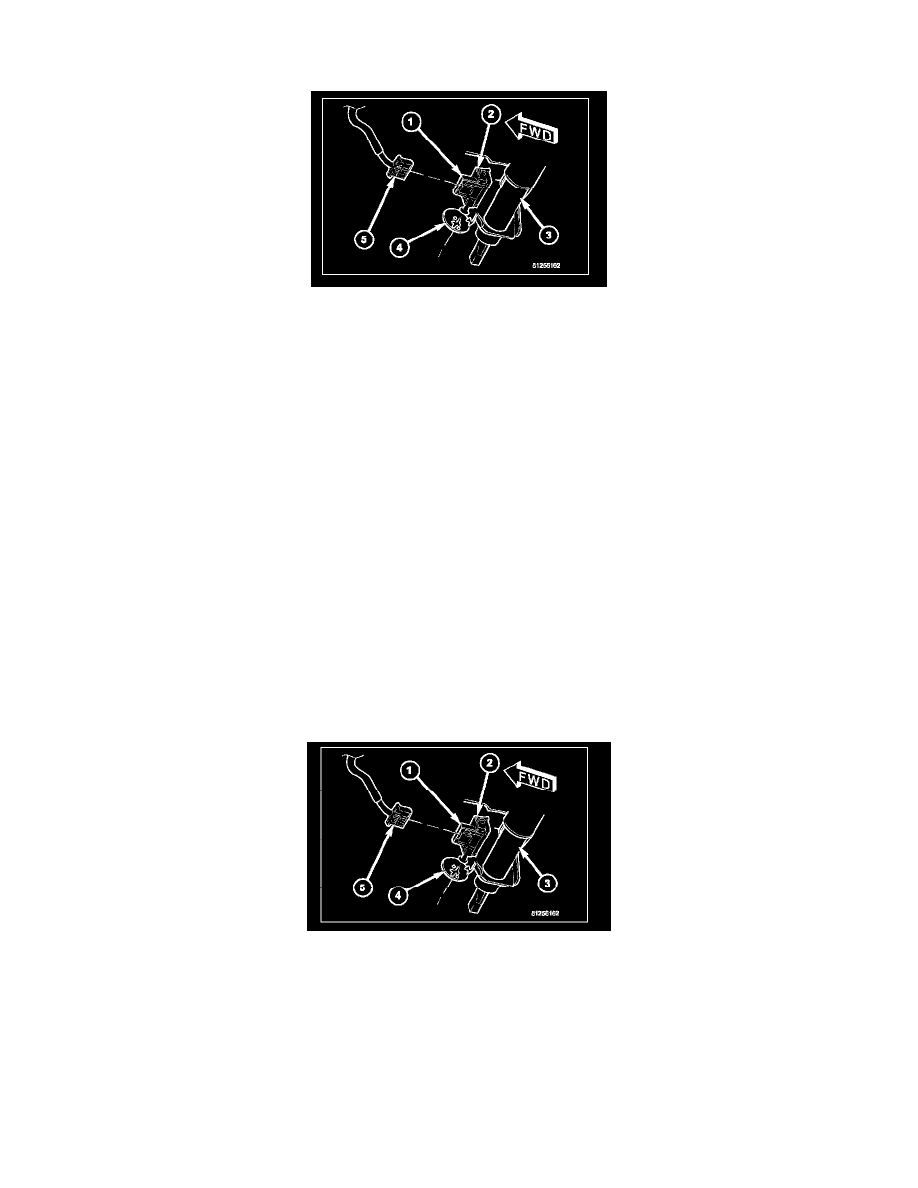
2. Locate the brake lamp switch (1) near the support bracket on the lower steering column (3).
3. Disconnect the wire harness connector (5) from the brake lamp switch.
4. Rotate the brake lamp switch housing clockwise about 30 degrees to align the tabs on the switch locking collar with the keyed hole in the switch
mounting bracket (4).
5. Pull the switch straight back from the keyed hole to remove it from the bracket.
CAUTION: The brake lamp switch self-adjusting switch plunger is a one time only feature. If the switch is removed from the mounting
bracket, it MUST be replaced with a new switch.
6. Discard the removed brake lamp switch.
INSTALLATION
WARNING: To avoid personal injury or death, on vehicles equipped with airbags, disable the supplemental restraint system before attempting
any steering wheel, steering column, airbag, seat belt tensioner, impact sensor, or instrument panel component diagnosis or service. Disconnect
and isolate the battery negative (ground) cable, then wait two minutes for the system capacitor to discharge before performing further
diagnosis or service. This is the only sure way to disable the supplemental restraint system. Failure to take the proper precautions could result
in accidental airbag deployment.
CAUTION: The brake lamp switch self-adjusting switch plunger is a one time only feature. If the switch is removed from the mounting
bracket, it MUST be replaced with a new switch.
1. Depress and hold the brake pedal in the depressed position.
2. Align the tabs on the brake lamp switch locking collar with the keyed hole in the switch mounting bracket (4) on the lower steering column (3).
3. Insert the tabs on the brake lamp switch locking collar through the keyed hole in the switch mounting bracket until the switch housing (1) is firmly
seated against the bracket.
4. Rotate the switch housing counterclockwise about 30 degrees to engage the tabs on the locking collar with the switch mounting bracket.
CAUTION: Do not release or pull up on the brake pedal before the switch plunger adjustment has been completed.
5. Release the brake pedal, but do not pull it upward.