
Raider 4WD V6-3.7L SOHC (2007)
Brake Light Switch: Description and Operation
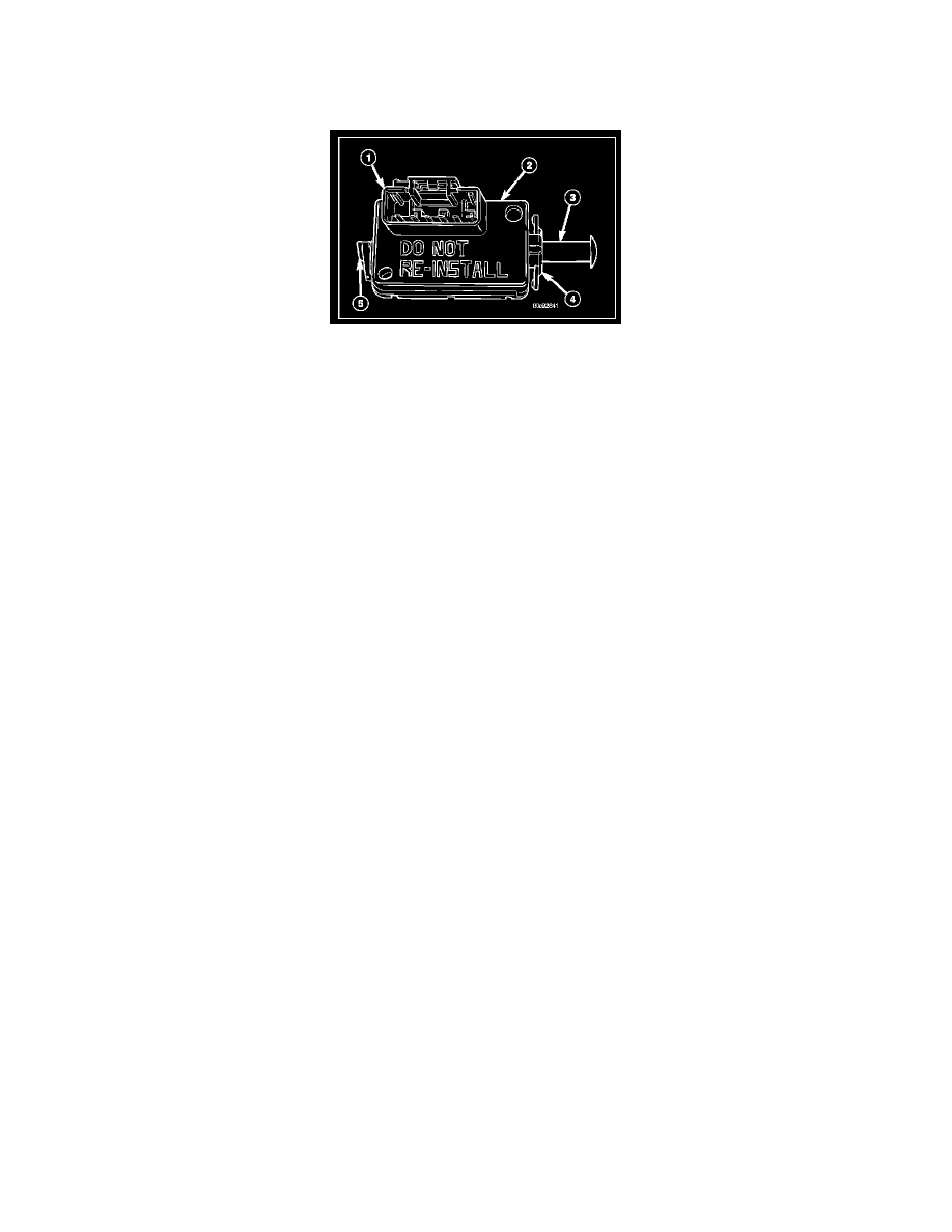
SWITCH - STOP LAMP
DESCRIPTION
The brake lamp switch (2) is a three circuit, spring-loaded plunger actuated switch that is secured to the steering column support bracket under the
instrument panel on the driver side of the vehicle. The molded plastic switch housing has an integral connector receptacle (1) containing six terminal pins
and featuring a Connector Position Assurance (CPA) lock. The switch is connected to the vehicle electrical system through a dedicated take out of the
instrument panel wire harness. The switch plunger (3) extends through a mounting collar (4) on one end of the switch housing. The plunger has a one
time telescoping self-adjustment feature that is activated after the switch is installed by moving an adjustment release lever (5) on the opposite end of the
switch housing clockwise, until it locks into a position that is horizontal and parallel to the connector receptacle. An installed brake lamp switch cannot
be readjusted or repaired. If the switch is damaged, ineffective, or removed from its mounting position for any reason, it must be replaced with a new
unit.
OPERATION
The brake lamp switch controls three independent circuits. These circuits are described as follows:
-
Brake Lamp Switch Circuit - A normally open brake lamp switch circuit receives a battery voltage input, and supplies this battery voltage to the
brake lamps and the Controller Antilock Brake (CAB) on a brake lamp switch output circuit only when the brake pedal is depressed (brake lamp
switch plunger released).
-
Brake Lamp Switch Signal Circuit - A normally closed brake lamp switch signal circuit receives a direct path to ground, and supplies this
ground input to the Powertrain Control Module (PCM) on a brake lamp switch sense circuit only when the brake pedal is released (brake lamp
switch plunger is depressed).
-
Speed Control Circuit - A normally closed speed control circuit receives a battery voltage input from the Powertrain Control Module on a speed
control supply circuit, and supplies this battery voltage to the speed control servo solenoids (dump, vacuum, and vent) on a speed control brake
switch output circuit only when the speed control system is turned ON and the brake pedal is released (brake lamp switch plunger is depressed).
The components of the self-adjusting brake switch plunger consist of a two-piece telescoping plunger, a split plunger locking collar, and a release
wedge. The release lever has a shaft with a wedge that spreads the plunger locking collar to an open or released position. After the switch is
installed and the brake pedal is released, the plunger telescopes to the correct adjustment position. When the release lever is moved to the release
position, the wedge is disengaged from the locking collar causing the collar to apply a clamping pressure to the two plunger halves, fixing the
plunger length. The brake lamp switch as well as the hard wired inputs and outputs of the switch may be diagnosed using conventional diagnostic
tools and procedures. Refer to the appropriate wiring information.