
Raider 4WD V6-3.7L SOHC (2007)
Vehicle Theft Secturity System
The Vehicle Theft Security System (VTSS) is designed to provide perimeter protection against unauthorized use or tampering by monitoring the vehicle
door ajar circuits, the power lock and unlock circuits, and the ignition switch circuit. If unauthorized use or tampering is detected, the system responds by
pulsing the horn for up to about 3 minutes and flashing the hazard warning lamps for up to about 18 minutes.
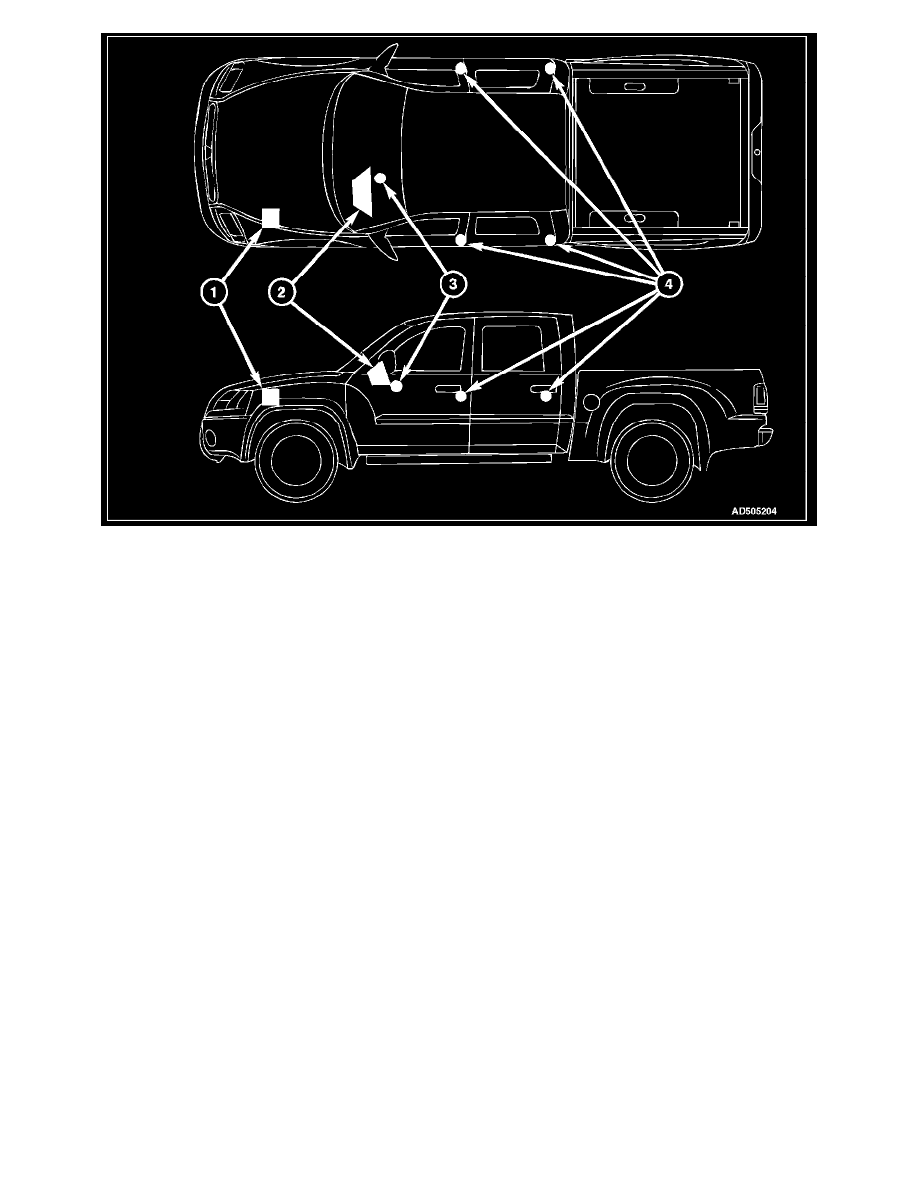
The VTSS includes the following major components, which are described in further detail elsewhere in this service information:
-
Door Ajar Switches (4) - A door ajar switch is integral to the door latch mechanism of each front door as well as the rear doors on double cab
vehicles. (Refer to LAMPS/ DOOR AJAR SWITCH/DESCRIPTION).
-
Electromechanical Instrument Cluster (2) - The Electromechanical Instrument Cluster (EMIC) is also known as the Cab Compartment Node
(CCN) in this vehicle. The EMIC/CCN is located in the instrument panel above the steering column opening, directly in front of the driver.
-
Front Control Module (1) - The Front Control Module (FCM) is integral to the Integrated Power Module (IPM). The FCM/IPM is located in the
engine compartment, near the battery and the Power Distribution Center (PDC).
-
Horn Relay - The horn relay is located in the Power Distribution Center (PDC) in the engine compartment near the battery.
-
Ignition Switch (3) - The ignition switch is located on the steering column in the passenger compartment.
-
Security Indicator - The security indicator is integral to the Electromechanical Instrument Cluster (EMIC) (also known as the Cab Compartment
Node/CCN).
Hard wired circuitry connects the VTSS components to the electrical system of the vehicle. These hard wired circuits are integral to several wire
harnesses, which are routed throughout the vehicle and retained by many different methods. These circuits may be connected to each other, to the vehicle
electrical system and to the VTSS components through the use of a combination of soldered splices, splice block connectors, and many different types of
wire harness terminal connectors and insulators. Refer to the appropriate wiring information. The wiring information includes wiring diagrams, proper
wire and connector repair procedures, further details on wire harness routing and retention, as well as pin-out and ocation views for the various wire
harness connectors, splices and grounds.
SENTRY KEY IMMOBILIZER SYSTEM
The Sentry Key Immobilizer System (SKIS) is designed to provide passive protection against unauthorized vehicle use by disabling the engine after
about two seconds of running, whenever any method other than a valid Sentry Key is used to start the vehicle. The SKIS is considered a passive
protection system because it is always active when the ignition system is energized and does not require any customer intervention. The SKIS uses Radio
Frequency (RF) communication to obtain confirmation that the key in the ignition switch is a valid key for operating the vehicle. The
microprocessor-based SKIS hardware and software also uses electronic messages to communicate with other electronic modules in the vehicle over the
Controller Area Network (CAN) data bus.