
Raider 4WD V6-3.7L SOHC (2007)
Windshield Washer Pump: Description and Operation
PUMP - WASHER - WINDSHIELD
DESCRIPTION
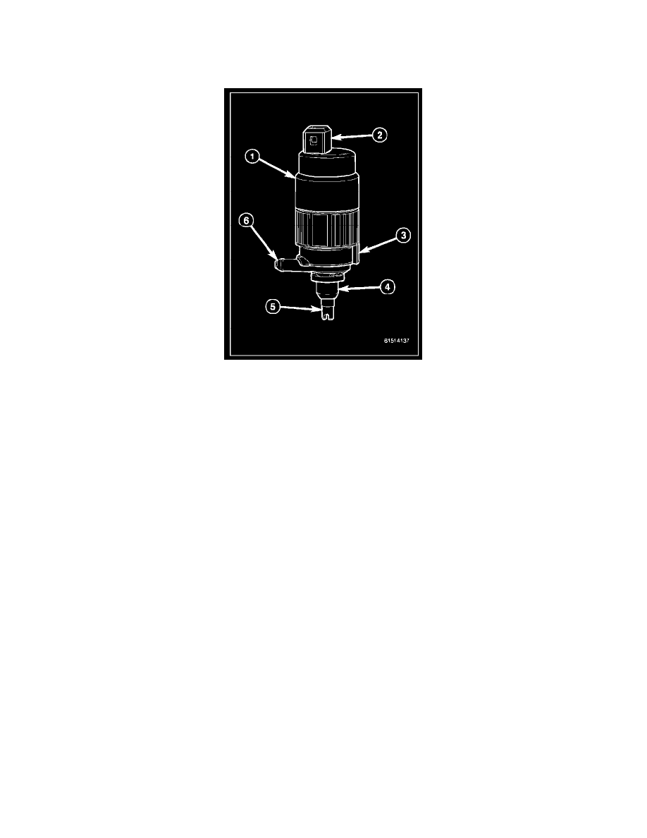
The washer pump/motor unit (1) is located on the top of a sump area on the outward facing side of the combination washer reservoir/coolant reserve
bottle, ahead of the right front fender wheel house splash shield. A small permanently lubricated and sealed electric motor is coupled to the rotor-type
washer pump (3).
An inlet nipple (5) on the bottom of the pump housing passes through a rubber grommet seal (4) installed in a dedicated mounting hole of the washer
reservoir. When the pump is installed in the reservoir the barbed outlet nipple (6) on the pump valve body housing points rearward and connects the unit
to the reservoir washer hose, which is engaged in an integral trough molded into the reservoir/bottle unit.
The washer pump/motor unit is retained on the reservoir by the interference fit between the pump inlet nipple and the grommet seal, which is a light
press fit. The top of the washer pump is also secured to the washer reservoir by a light snap fit into a receptacle molded into the reservoir that allows for
mounting of the washer pump without the use of fasteners. An integral connector receptacle (2) on the top of the motor housing connects the unit to the
vehicle electrical system through a dedicated take out and connector of the headlamp and dash wire harness.
The washer pump/motor unit cannot be repaired. If ineffective or damaged, the entire washer pump/motor unit must be replaced.
OPERATION
The washer pump/motor unit features a small Direct Current (DC) electric motor. The motor is connected to the vehicle electrical system through a
single take out and two-cavity connector of the headlamp and dash wire harness. The motor is grounded at all times through another take out of the
headlamp and dash wire harness with a single eyelet terminal connector that is secured by a nut to a ground stud located on the right front fender inner
shield in the engine compartment.
The motor receives battery current on a washer pump/motor control circuit. The washer pump/motor control circuit is energized through a high side
driver within the Front Control Module (FCM) whenever the FCM receives an electronic message requesting washer system operation from the
ElectroMechanical Instrument Cluster (EMIC) (also known as the Cab Compartment Node/CCN) over the Controller Area Network (CAN) data bus.
The EMIC monitors a resistor multiplexed hard wired input from the momentary washer switch contacts within the multifunction switch on the steering
column to determine when it should issue the electronic message requesting washer system operation.
Washer fluid is gravity-fed from the washer reservoir to the inlet side of the washer pump. When the pump motor is energized, the motor spins the rotor
within the washer pump. The spinning pump rotor pressurizes the washer fluid and forces it through the pump outlet nipple, the washer plumbing, and
the washer nozzles onto the windshield glass.
The washer pump/motor unit and the hard wired motor control circuits from the FCM may be diagnosed using conventional diagnostic tools and
procedures. Refer to the appropriate wiring information. However, conventional diagnostic methods will not prove conclusive in the diagnosis of the
washer pump/motor unit or the electronic controls or communication between other modules and devices that provide some features of the wiper and
washer system. The most reliable, efficient, and accurate means to diagnose the washer pump/motor unit or the electronic controls and communication