
Starion L4-2555cc 2.6L SOHC Turbo (1988)
Throttle Position Sensor: Adjustments
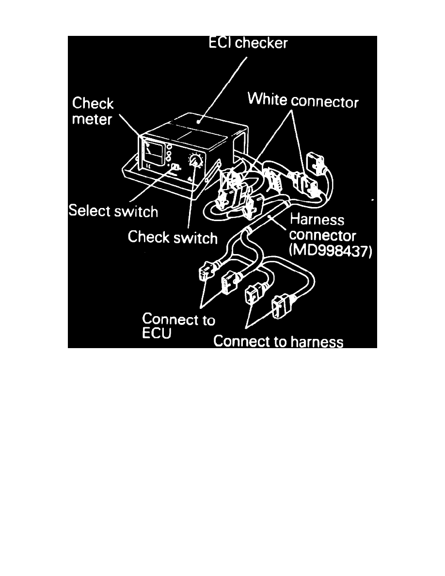
Fig. 21 ECI system tester
1987 - 88 Models
1.
Start and run engine at fast idle to bring coolant to normal operating temperature (185 to 205°F), then turn ignition ``Off.''
2.
Ensure all lights, accessories and electric cooling fan are ``Off,'' then place transaxle in Neutral position.
3.
Place steering wheel in a straight ahead position.
4.
Loosen accelerator cable, then connect a suitable tachometer to engine according to manufacturers' instructions.
5.
Turn ignition switch to ``Lock'' position, then disconnect TPS wiring connector.
6.
Jump connector using suitable jumper wires, ensuring not to allow wires to contact each other.
7.
Using a suitable digital voltmeter, connect leads to jumper wires representing green wire with black stripe and green wire with red stripe.
8.
Attach a suitable tachometer to engine according to manufacturers' instructions.
9.
On Mirage models, proceed as follows:
a. Turn ignition switch On, the hold switch, but do not start engine, and hold in position for approximately 15 seconds to check that ISC motor
is in idle or initial position. Initial position represents idle opening or .9 volts of motor position sensor output voltage.
b. Turn ignition switch to ``Lock'' position, then disconnect ISC servo connector, then ensure ISC motor is in initial position.
c. Open throttle valve halfway two or three times, then release to allow it to snap closed. Loosen fixed SAS.
d. Start and idle engine, then check idle speed. Idle speed should be 700 RPM.
e. If idle speed is not as specified, adjust ISC adjusting screw until specified idle speed is obtained. When rotating ISC adjusting screw, use
the appropriate tool and only make adjustments to specifications in the tightening direction.
10.
On Starion models, proceed as follows:
a. Turn ignition switch to ``Lock'' position, then remove large harness connector.
b. Set check switch on ECI checker to ``Off,'' then the select switch to A.
c. Connect white color connectors labeled ``Checker,'' of harness connector to connectors of ECI checker. Connect harness connector to ECU