
Tredia L4-1795cc 1.8L SOHC Turbo (1984)
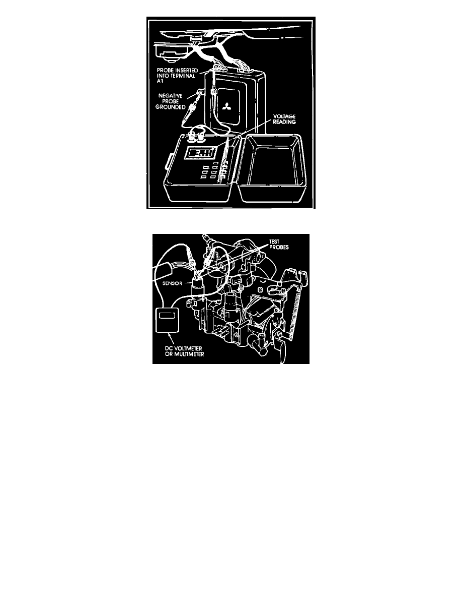
Figure 2
Figure 3
TEST PROCEDURE
1.
Remove the right side kick panel and the trim panel below the glovebox to reach the computer terminal connectors.
2.
Attach the black lead of your voltmeter to a good ground - the computer box is good.
3.
Refer to the appropriate ECI Voltmeter Check Charts I and II for the car you are checking. Note the connector terminal callouts in the right
column. Insert the positive probe into each connector terminal in turn. Switch the ignition from OFF to ON, and compare the voltage with that
shown in the chart. For example, when the probe is on terminal A1, the voltmeter should read between 0 and 0.6V as shown in Fig. 2 with the
accelerator closed, and 4-5V when the accelerator is open.
4.
Proceed until you have checked all the terminals in Chart 1, or until a voltage is found that is out of specification. If you obtain a voltage reading
out of specification, go to Step 5. If all voltages are within specification, go to Step 6.
5.
When you find a voltage that is out of specification (except TPS), measure sensor voltage output at the sensor terminal of the same color wire as in
the computer terminal for that sensor. Fig-
ure 3 shows a typical example. This tells you whether the voltage variation is in the sensor or in connectors and wiring.
Correct any loose connections, replace sensors as required, and then disconnect the battery for 30 seconds to erase the computer's memory of the
malfunction. Re-check the appropriate terminal to verify that the malfunction has been corrected.
NOTE:
If the TPS voltage is out of specification, remember that the TPS produces a failure signal if the throttle is blipped when shutting down the engine.
Restart the engine and then let it stop it stop without depressing the accelerator. Measure the TPS voltage at the computer, and, if necessary, at the
sensor connector.
6.
Perform the checks in Chart II. If an out-ofspecification voltage is found, locate the sensor and measure its output right at the connector. If OK,
then you know the wiring or connector is the source of the discrepancy.