
Tredia L4-1795cc 1.8L SOHC Turbo (1984)
Data Link Connector: Technical Service Bulletins
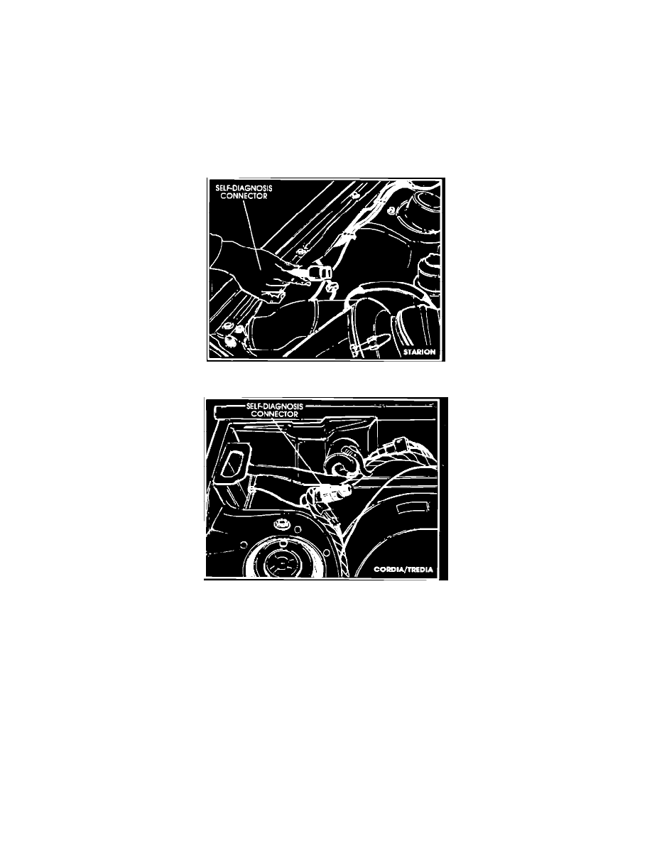
ECI - Self-Diagnosis/Test Connector Location
NO.
STB-84-14-013
DATE
June, 1984
MODEL 1984 Starion; 1984 Turbo Cordia/Tredia
SUBJECT:
ECI SELF-DIAGNOSIS TEST PROCEDURE
Figure 1
Figure 2
NEW SELF-DIAGNOSIS CONNECTOR LOCATION
In 1984 Starions and Turbo Cordia/Tredia models built since December, 1983, the ECI self-diagnosis connector has been relocated to a more convenient
location under the hood. Figure 1 shows the location for Starion. Figure 2 shows the location for Cordia/Tredia. On earlier 1984 models, the connector is
under the dash near the ECI computer. (1983 models do not have the self-diagnosis feature.)
Although the self-diagnosis system and procedure are completely designed in the 1984 Starion and Cordia/ Tredia Service Manuals, the procedures in
the Service Manuals are designed for the ECI checker. This bulletin presents a procedure for performing the self-diagnosis test with a LED test light or a
high-impedance voltmeter.
WHAT IS SELF-DIAGNOSIS?
Self-diagnosis is the ability of the ECI computer to tell you when a sensor output signal is or has been outside its specified range. The self-diagnosis
signal is available any time the ignition is ON.
The self-diagnosis circuitry has a "memory." This means that if a sensor voltage has been out of the specified range any time in the past, the memory of
that "failure" is retained, until erased. For example, if a sensor is disconnected any time the ignition is ON, a failed code is retained in memory even