
Tredia L4-1795cc 1.8L SOHC Turbo (1984)
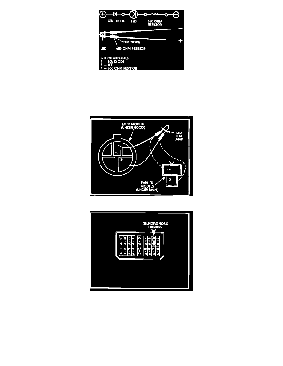
Figure 4
HOW TO PERFORM THE SELF-DIAGNOSIS TEST
1.
You will need a LED test light or a high-impedance analog (not digital) voltmeter for the selfdiagnosis test. (An ordinary test light or
low-impedance voltmeter can conduct enough current to damage sensitive electronic circuitry, and their use must be avoided.) You can make a
LED test light for about $2.00 with materials and circuitry shown in Fig. 4.
Figure 5
Figure 6
2.
Locate the self-diagnosis connector, or remove cowl kick panels and underdash trim to reach the A-16 terminal cavity in the ECI computer
connector. (The A-16 terminals is the self-diagnosis terminal on all 1984 models.)
Connect the voltmeter or LED test light to the selfdiagnosis connector as shown in Fig. 5 or to the A-16 terminal (+) and ground (-) as shown in Fig. 6.
3.
Turn the ignition ON and observe the LED test light or voltmeter. Count the number of blinks of the light or swings of the needle and refer to the
chart on page 2 to determine which sensor circuit is out of specifications. NOTE:
If you get a code 1, the computer is OK. To test the oxygen sensor, warm up the engine and then drive long enough to get the oxygen sensor working.
Then, without shutting off the engine, conduct the self-diagnosis test.