
Achieva L4-144 2.4L DOHC VIN T SFI (1996)
PCM Input Sensors
Diagnosis
^
The following tables will diagnose the oil level switch, the oil pressure switch and the coolant level switch circuits.
^
For diagnosis of the fuel pump circuitry portion of the fuel pump and engine oil level switch, refer to Engine Cranks but Does Not Run. See:
Powertrain Management/Computers and Control Systems/Testing and Inspection
^
For diagnosis of the Instrument Panel Cluster (IPC), refer to Instrument Panel. See: Instrument Panel, Gauges and Warning Indicators
^
For PCM replacement information, refer to PCM / Replacement/Programming. See: Powertrain Management/Computers and Control
Systems/Powertrain Control Module
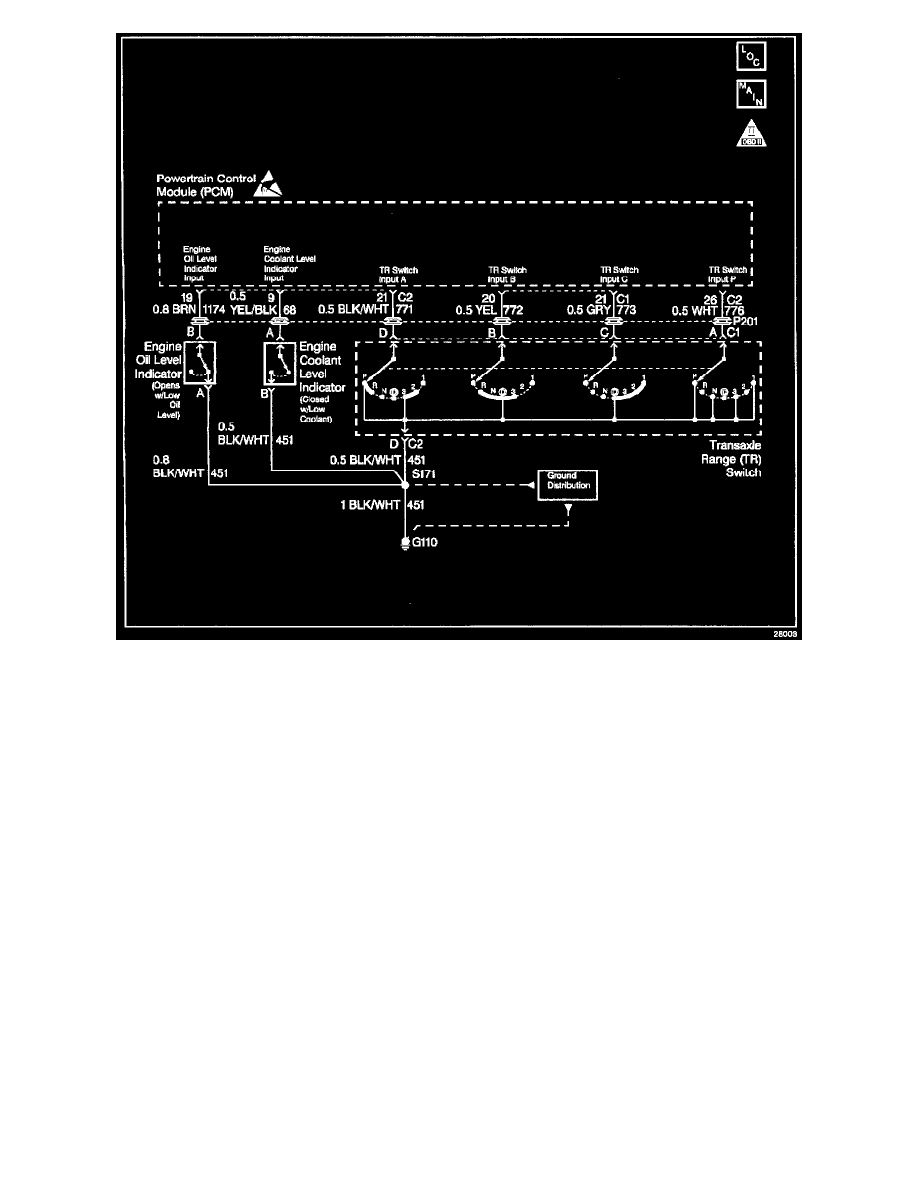
Circuit Description
The coolant level switch is an assembly containing a reed switch and magnetic float. When the coolant level is normal, the float rests away from the reed
switch, causing the switch to open. When the coolant level is low, the float rests near the reed switch and the switch closes.
The coolant level switch is mounted in the radiator surge tank. If the coolant level falls below a specified level, the switch closes sending a ground signal
to the Powertrain Control Module (PCM). The PCM will then send this signal to the Instrument Panel Cluster (IPC). The PC will then illuminate the low
coolant level telltale lamp.
Diagnostic Aids
^
Quick test: Disconnect the coolant level switch electrical connector. With a test light connected to ground, probe the signal circuit. This will
cause the coolant level indicator to turn ON if the wiring, PCM and IPC are OK.
^
An Intermittent problem may be caused by a poor connection, rubbed through wire insulation,