
Achieva L4-144 2.4L DOHC VIN T SFI (1996)
Powertrain Control Module: Description and Operation
General System Description
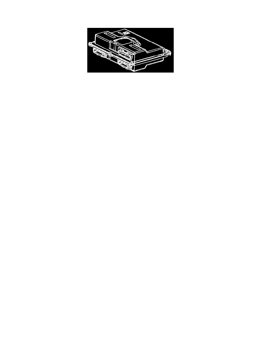
Powertrain Control Module (PCM)
The Powertrain Control Module (PCM), located under the instrument panel, is the control center of the fuel injection system. It constantly looks at
the information from various sensors, and controls the systems that affect emission or engine performance. The PCM also performs the diagnostic
function of the system. It can recognize operational problems, alert the driver through the Malfunction Indicator Lamp (MIL), and store a DTC or
DTC's which identify the problem areas to aid the technician in making repairs.
The PCM used on the OBD II LD9 (2.4L) engine is referred to as PCM-6SU. For service, this PCM only consists of two parts: a controller (the
PCM without a KS module) and Knock Sensor (KS) module.
The control module has a "learning" ability which allows the control module to make corrections for minor variations in the fuel system in order to
improve driveability. Whenever the battery cable is disconnected, the "learning" process resets.
The driver may note a change in the vehicle's performance. In order to allow the PCM to "re-learn" to drive the vehicle at part throttle with
moderate acceleration. The vehicle may also operate at idle conditions until the normal performance returns.
PCM FUNCTION
The Powertrain Control Module (PCM) supplies either 5 or 12 volts to power various sensors or switches. This is done through resistances in the
PCM which are so high in value that a test light will not light when connected to the circuit. In some cases, even an ordinary shop voltmeter will
not give an accurate reading because its resistance is too low. Therefore, a 10 megohm input impedance digital voltmeter is required to assure
accurate voltage readings.
The Powertrain Control Module (PCM) controls most components with electronic switches which complete a ground circuit when turned ON.
These switches are arranged in groups of 4 and 7, called either a surface mounted quad driver module, which can independently control up to 4
outputs (PCM terminals), or output driver modules, which can independently control up to 7 outputs. Not all outputs are always used.
PCM PROGRAMMING
Refer to the latest Techline information on re-programming procedures.
PASSWORD LEARN PROCEDURE
In order for a theft deterrent vehicle to run, a password is communicated between the Instrument Panel Cluster (IPC) and the PCM. If a PCM is
replaced, the new PCM needs to learn the correct password of the vehicle. When the new PCM is installed, the EEPROM calibration is flashed
into the new PCM and the vehicle will learn the new password upon initial ignition ON. If the IPC is replaced, the PCM needs to learn the new
password from the IPC. The password learn procedure is as follows:
1. Attempt to start vehicle, then leave the ignition ON. The THEFT SYSTEM telltale will flash for 10 minutes.
2. When the THEFT SYSTEM telltale stops flashing, start the vehicle. Once the vehicle is running, the password is learned.