
Achieva V6-3100 3.1L MFI VIN M (1994)
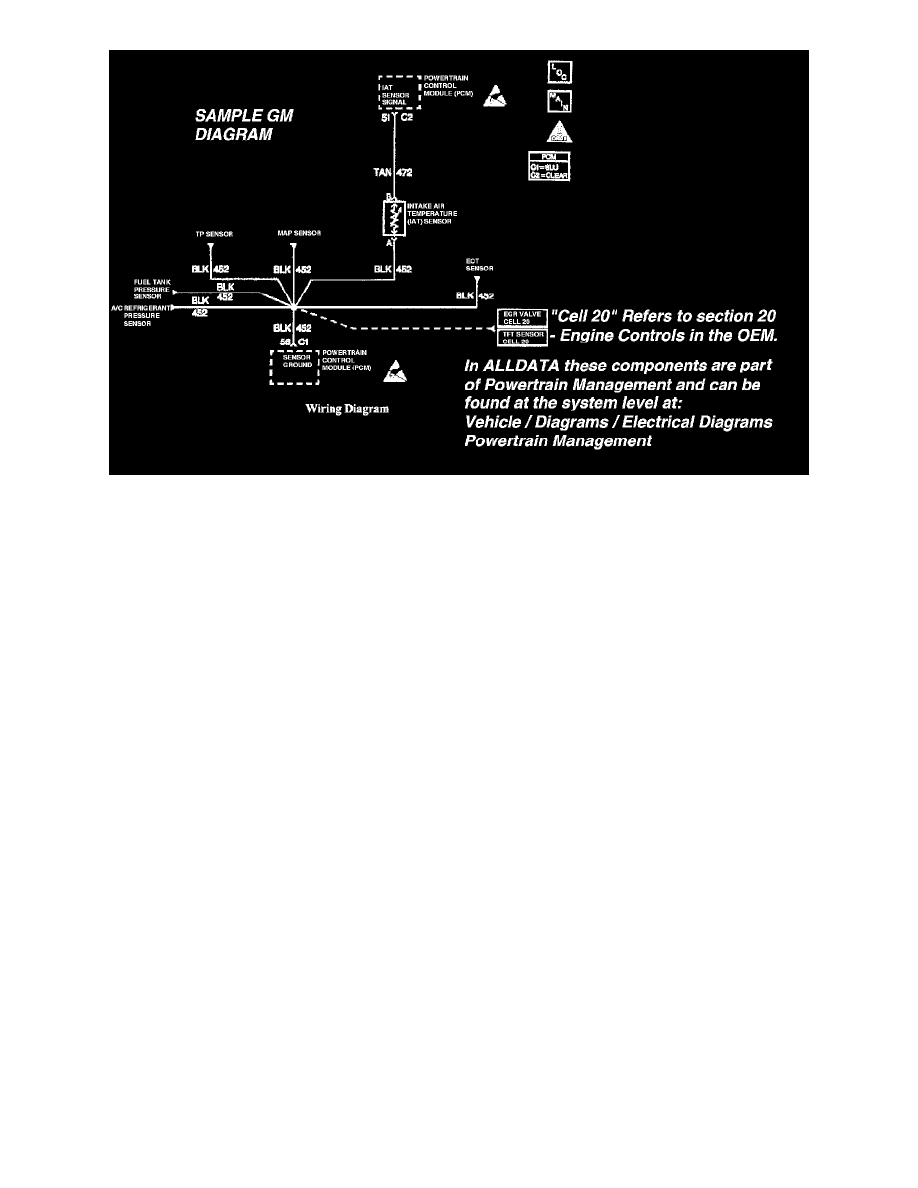
GM Sample Diagram W/ Cell Reference
For instance, in the diagram illustrated "Cell 20" is not a reference to another diagram but a reference to "Section 20" in the OE manual. In the
example, "Section 20" is the engine control section of the manual.
To navigate through these "Cell" references start at the vehicle level and go to: Diagrams / Electrical Diagrams - for a complete list of the diagrams
available for the vehicle. Choose the system you are working on and view those diagrams.
Note: If unsure of the system - try utilizing the search feature. Type a component in the search feature that belongs to the system and when the
results are displayed note the path displayed. This will show the system the component belongs in.
Circuit Protection Devices
DESCRIPTION:
The purpose of circuit protection is to protect the wiring assembly during normal and overload conditions. An overload is defined as a current
requirement that is higher than normal. This overload could be caused by a short circuit or system malfunction. The short circuit could be the
result of a pinched or cut wire or an internal device short circuit, such as an electronic module failure.
The circuit protection device is only applied to protect the wiring assembly, and not the electrical load at the end of the assembly. For example, if
an electronic component short circuits, the circuit protection device will assure a minimal amount of damage to the wiring assembly. However, it
will not necessarily prevent damage to the component.
CIRCUIT PROTECTION DEVICES
There are three basic types of circuit protection devices: Circuit Breaker, Fuse and Fusible Link.
CIRCUIT BREAKERS
A circuit breaker is a protective device designed to open the circuit when a current load is in excess of rated breaker capacity. If there is a short or
other type of overload condition in the circuit, the excessive current will open the circuit between the circuit breaker terminals. There are two basic
types of circuit breakers used in GM vehicles: cycling and non-cycling.
CYCLING CIRCUIT BREAKER
The cycling breaker will open due to heat generated when excessive current passes through it for a period of time. Once the circuit breaker cools,
it will close again after a few seconds. If the cause of the high current is still present it will open again. It will continue to cycle open and closed
until the condition causing the high current is removed.
NON-CYCLING CIRCUIT BREAKER
There are two types of non-cycling circuit breakers. One type is mechanical and is nearly the same as a cycling breaker. The difference is a small
heater wire within the non-cycling circuit breaker. This wire provides enough heat to keep the bimetallic element open until the current source is
removed. The other type is solid state, known as an Electronic Circuit Breaker (ECB). This device has a Positive Temperature Coefficient. It
increases its resistance greatly when excessive current passes through it. The excessive current heats the ECB. As it heats, its resistance increases,