
Achieva V6-3100 3.1L MFI VIN M (1994)
circuit should work, before trying to figure out why it doesn't.
After you understand how the circuit should operate, read the schematic again, this time keeping in mind what you have learned by operating
the circuit.
Since both LO beams work, you know that the Headlight Switch, the YEL wire, the LO contacts of the Headlight Dimmer Switch, terminal
"1E" of C100, the TAN wires and grounds G105 and G109 are all good.
Furthermore, since you saw that the HI Beam Indicator came on when the headlight Dimmer Switch was moved to "HI," you know that the HI
contacts of the Headlight Dimmer Switch and the LT GRN wire between the Headlight Dimmer Switch and C100 are good.
At this point, you could test for voltage at the RH Headlamp with the Headlight Dimmer Switch in "HI." However, it is extremely unlikely that
the HI beam filaments have burned out in both headlamps, or that both headlamps connections are bad. The cause must be a bad connection at
C100, or a break in the LT GRN wire between C100 and the RH Headlamp.
You have quickly narrowed the possible causes down to one specific area, and have done absolutely no work on the vehicle itself.
Step 3:
Find the fault and repair it. Using the Component Location List and the corresponding figure, you can quickly find C100 and the LT GRN
wire, locate the exact trouble point and make the repair.
Step 4:
Check the repair by performing a system check on the headlights circuit. This, of course, means making sure that both HI beams, both LO
beams and the HI Beam Indicator are all working.
Now suppose that the symptoms were different. You may have operated the Headlamps and found that the LO beams were working, but
neither the HI beams nor the HI Beam Indicator were working. Looking at the schematic, you might conclude that it is unlikely that both HI
beam filaments and the HI Beam Indicator have all burned out at once. The cause is probably the Headlight Dimmer Switch or its connector.
Troubleshooting Tests
PROBING
After probing, when reconnecting connectors or replacing terminals, always be sure to reinstall Connector Position Assurance (CPA) and
Terminal Position Assurance (TPA).
Frontprobe
When frontprobing of connectors is required, always use a mating terminal adapter (GM Connector Test Adapter Kit J 35616 or equivalent).
The use of proper adaptors will ensure that proper terminal contact integrity is maintained.
Backprobe
Only backprobe connector terminals when specifically called for in diagnostic procedures. Since backprobing can be a source of damage to
connector terminals, extra care must be taken to avoid deforming the terminal, either by forcing the test probe too far into the cavity or by
using too large a test probe.
After backprobing any connector, always check for terminal damage. If terminal damage is suspected, check for proper terminal contact, see
Checking Terminal Contact.
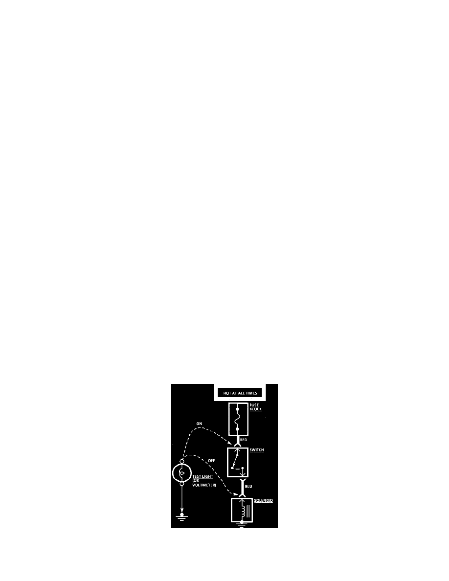
Voltage Check
TESTING FOR VOLTAGE