
Achieva V6-3300 3.3L (1992)
Hydraulic Modulator Assembly: Service and Repair
Hydraulic Modulator/Master Cylinder Assembly Repair
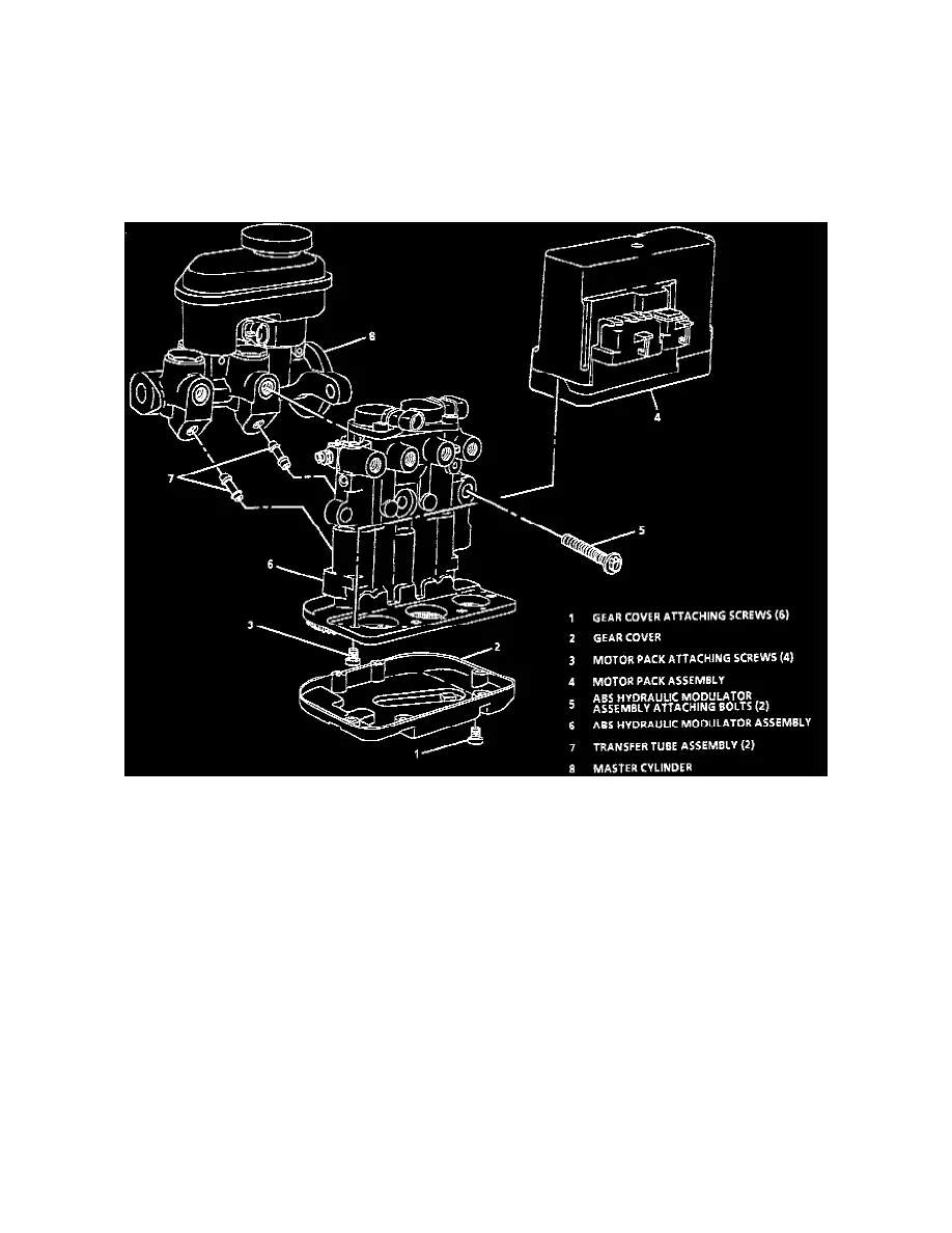
ABS Hydraulic Modulator and Master Cylinder Assembly Components
ABS HYDRAULIC MODULATOR AND MASTER CYLINDER ASSEMBLY COMPONENTS
CAUTION: To help avoid personal injury, due to a retained load on the ABS hydraulic modulator, the gear tension relief function of the Tech
1 must be performed prior to removal of the ABS hydraulic modulator/master cylinder assembly. Refer to "Gear Tension Relief Sequence".
ABS Hydraulic Modulator And Master Cylinder Assembly Components
DISASSEMBLE
1. Six Torx head screws attaching gear cover.
2. Gear cover.
3. Four Torx head screws attaching motor pack assembly.
IMPORTANT
^
Use care when handling motor pack assembly to ensure motor pack connector is not damaged, or accidental intrusion of brake fluid into the
motor pack does not occur as this may result in a premature failure of the motor pack assembly.
^
Take care in handling the motor pack assembly. If dropped or damaged during handling, the motor pack assembly must be replaced.
4. Remove motor pack assembly.
IMPORTANT
^
If disassembly of the ABS hydraulic modulator and master cylinder assembly was due to a ABS hydraulic functional test that did not pass, the
automated motor pack diagnosis test should be performed at this time to isolate the motor pack or ABS hydraulic modulator.
5. Two modulator assembly to master cylinder thru-bolts and separate modulator assembly from master cylinder.
6. Two transfer tubes with 0-rings from master cylinder or modulator assembly.
7. Thru-bolt 0-rings from master cylinder and modulator assemblies.