
Achieva V6-3300 3.3L (1992)
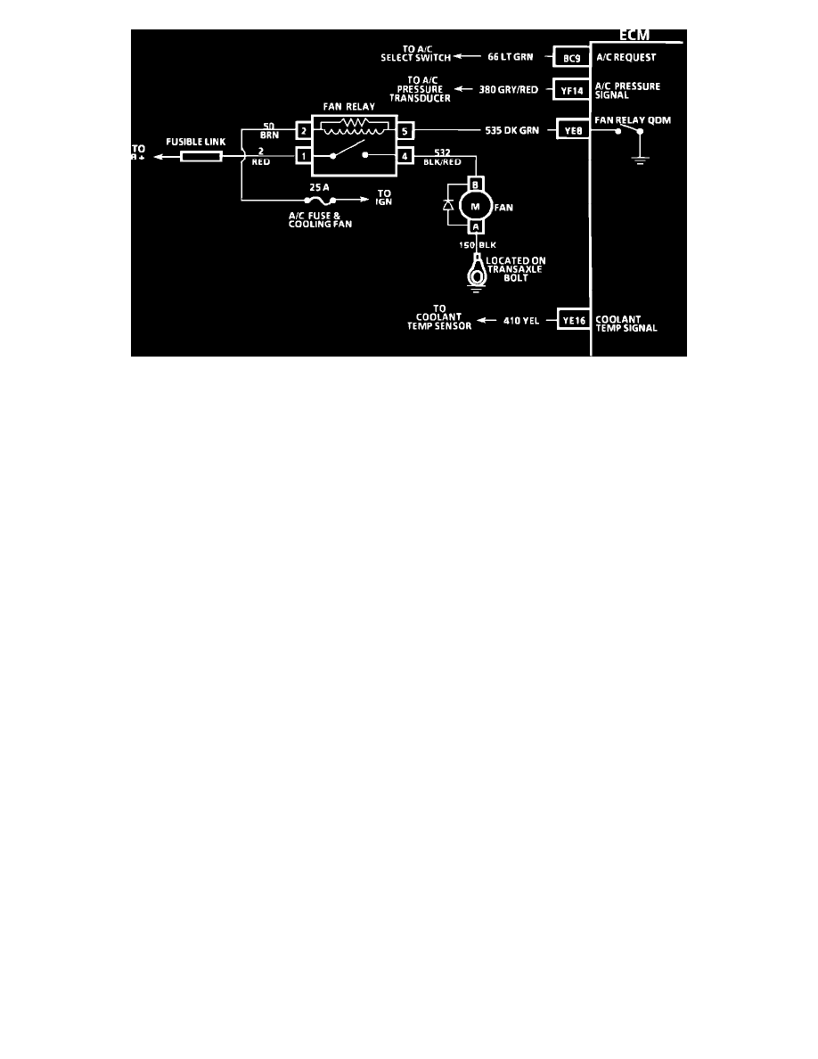
Chart C-12A Wiring Diagram
CIRCUIT DESCRIPTION:
Battery voltage to operate the cooling fan motor is supplied to relay terminal "1". Ignition voltage to energize the relay is supplied to relay terminal "2".
When the ECM grounds CKT 535, the relay is energized and the cooling fan is turned "ON". When the engine is running, the ECM will turn the cooling
fan "ON" if the conditions for a coolant temperature sensor trouble code (14 or 15) are present or:
^
The A/C pressure is at a calibrated value
^
The coolant temperature is greater than 100~C (212~F).
TEST DESCRIPTION: Numbers below refer to circled numbers on the diagnostic chart.
1.
Terminal 2 should be B+ when the ignition is turned "ON". Terminal 1 is connected directly to B+.
2.
Test light should be "ON" as using the scan tool to turn the QDM "ON." This allows current to flow through the fan relay coil.
DIAGNOSTIC AIDS:
^
If the owner complained of an overheating problem, it must be determined if the complaint was due to an actual boilover, or the hot light, or
temperature gauge indicated over heating.
^
If the gauge, or light, indicates overheating, but no boilover is detected, the gauge circuit should be checked. The gauge accuracy can, also, be
checked by comparing the coolant sensor reading using "Scan" tool and comparing its reading with the gauge reading.
^
If the engine is actually overheating, and the gauge indicates overheating, but the scan tool indicates lower temperatures and the cooling fan is
not coming "ON", the coolant sensor has probably shifted out of calibration and should be replaced. Refer to "Coolant temperature vs.
Resistance values" table. See: Powertrain Management/Computers and Control Systems/Testing and Inspection/Diagnostic Trouble Code
Tests and Associated Procedures/Manufacturer Code Charts/DTC 14
Chart C-12B Coolant Fan Control Circuit