Achieva V6-3300 3.3L (1992)

1. Release lock assembly (2) to be sure it is in full open position (9). Do this by pushing up on outside lock rod lever (8) and pulling on inside lock
handle lever (4).
2. Before placing new actuator on lock assembly, you must first position plastic teeth of lock switch. Push teeth (13) fully toward actuator arm (11)
so they will mesh correctly with teeth on lock assembly when installed.
3. Verify that actuating arm rubber bumper (10) is on actuating arm (11). Install actuating arm and bumper into locking lever (12), align lock switch
teeth to gear tooth forkbolt (15) and align screw holes.
4. Attach two Torx(R) screws.
5. Manually operate lock assembly by pushing inward on fork bolt until it clicks into fully closed position (as shown). Lock must operate to fully
closed position without any interference.
6. Connect electrical connections and test operation of actuator and lock switch.
7. Lock assembly.
8. Be sure lock carrier is properly mounted and retained.
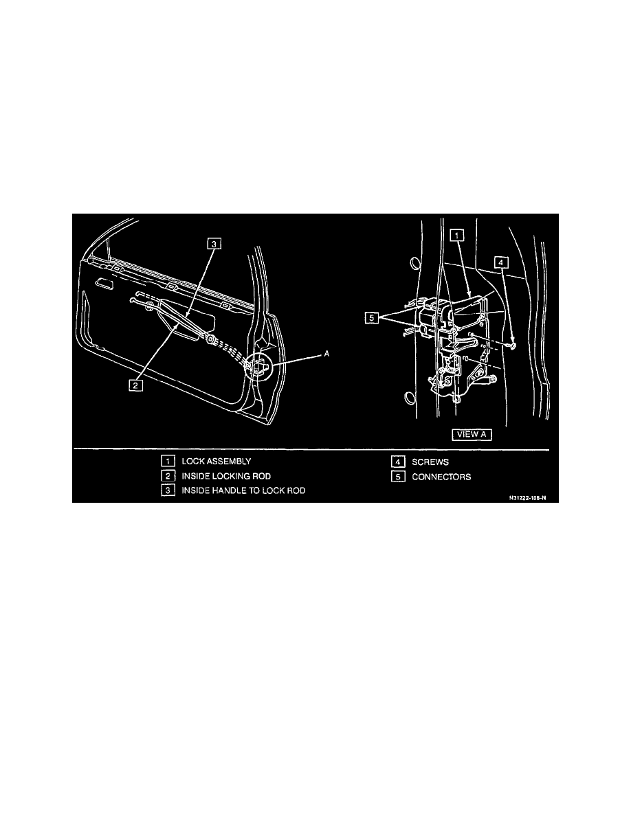
Lock Assembly
Remove or Disconnect
1. Door trim panel.
2. Water deflector.
3. Inside locking rod (2), inside handle to lock rod (3).
4. Outside door handle to lock rod, and lock cylinder rod.
5. Three screws (4).
6. Lock (1).
7. Electrical connectors (5).
Install or Connect
1. Electrical connectors (5).
2. Lock (1).
3. Three screws (4).
NOTICE: It is required that while performing step 2 the lock assembly be held tight against door facing while installing screws. All screws must be
driven at a 90 degree angle to door facing to prevent cross threading or stripping of screws or door lock attaching holes. It is also required to tighten
screws to 7 N.m (62 lbs. in.). DO NOT OVER TIGHTEN.
4. Outside door handle to lock rod, and lock cylinder to lock rod.
5. Inside handle to lock rod (3), and inside locking rod (2).
6. Water deflector.
