
Aurora V6-214 3.5L VIN H SFI (2001)
Crankshaft Position Sensor: Description and Operation
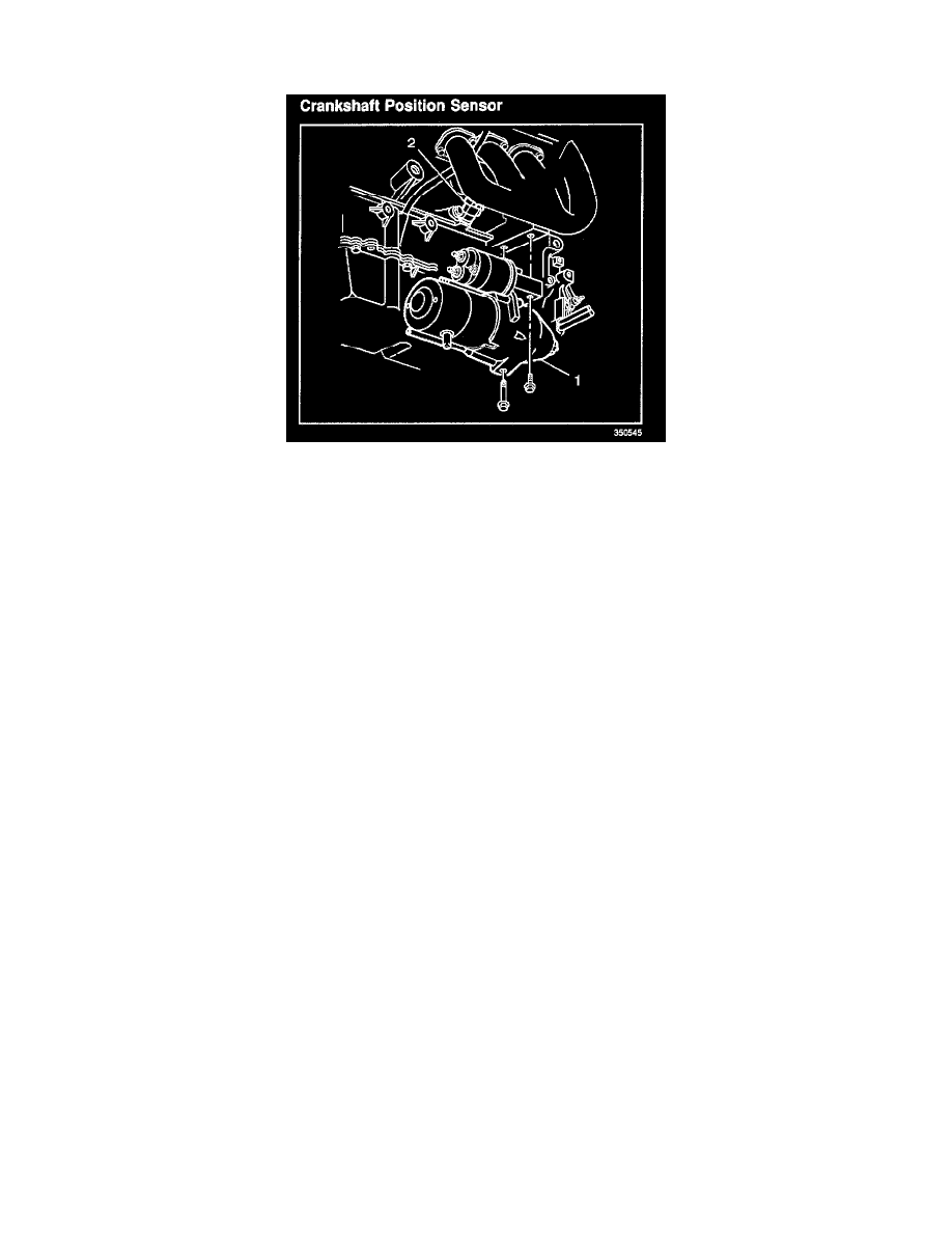
CRANKSHAFT POSITION SENSOR
Crankshaft Position Sensor
The Crankshaft Position (CKP) sensor (2) used on this engine is actually 2 sensors within a single housing. Each sensor has a separate power Circuit,
ground circuit, and signal circuit. The PCM supplies 12 volts to both sensors. The PCM provides the ground path, or sensor return circuit, from both
sensors. The power and ground circuits are also shared with the CMP sensor. Two separate signal circuits connect the CKP sensor and the PCM.
The PCM can use 3 different modes of decoding the crankshaft position. During normal operation, the PCM performs an Angle Based calculation using
both signals to determine the crankshaft position. The dual sensor allows the engine to run even if one signal is lost. If either signal is lost, the PCM
switches to a Time Based method of calculating the crankshaft position. If the system is operating in Time A mode, the PCM is using only the signal
from Sensor A. Time B indicates that the Sensor B signal is being used. If the lost signal is restored, the PCM will continue to operate in Time Based
mode for the remainder of the current key cycle. The PCM will revert back to the Angle Based mode on the next start if the fault is no longer present.
The scan tool can display the Crank Position Sensing Decode Mode. A problem with either sensor will set the appropriate DTC.