
Aurora V8-4.0L VIN C (1996)
CRANKSHAFT POSITION SENSORS AND RELUCTOR RING
Description
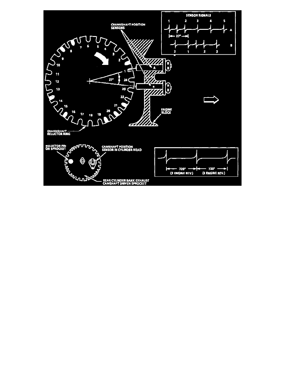
The two crankshaft sensors are located on the front bank (BANK 2) of the engine block between cylinders 4 and 6. Crankshaft position A sensor is
located in the upper crankcase and crankshaft position B sensor is located in the lower crankcase. Both sensors extend into the crankcase and are
sealed to the engine block with 0-rings. The crankshaft position sensors are not adjustable.
Operation
The magnetic crankshaft position sensors operate similar to the pickup coil in a distributor. When a piece of steel (called a reluctor) is repeatedly
moved over the sensor, a voltage will be created by the sensor that appears to go On-Off-On-Off-On-Off. This On-Off signal is also similar to the
signal that a set of breaker points in a distributor would generate as the distributor shaft turned and the points opened and closed.
The reluctor ring is cast onto the crankshaft between the #3 and #4 main bearing journals. The reluctor ring has 24 evenly spaced notches or air
gaps and an additional 8 unevenly spaced notches for a total of 32.
As the crankshaft makes one complete revolution, both the A and B sensors will produce 32 On-Off pulses per revolution. In addition, the A
sensor is positioned 27 of crankshaft revolution before the B sensor. This creates a unique pattern of On-Off pulses sent to the ignition control
module so that it can recognize crankshaft position.
^
The Crankshaft Reluctor Ring has 24 evenly spaced notches plus 8 additional notches (shaded) used for synchronization.
^
As the crankshaft rotates, the notches pass the position sensors and create a voltage pulse signal in the sensor that is an input for the Ignition
Control (IC) module.
^
Because of the physical location of the two crankshaft position sensors, the signal of "B" lags the signal of "A" by 27 of crankshaft revolution.
^
To synchronize the ignition, the IC module first counts the number of "B" pulses between every 2 "A" pulses. There can be 0,1 or 2 "B" pulses
between "A" pulses.
^
When the IC module sees 0 "B" pulses between "A" pulses , it starts counting "B" pulses between "A" pulses. When the IC module counts
exactly 4, it synchronizes the ignition on the very next "A" pulse. If the IC module counts over 4 (jumps from 3 to 5), it waits for another "B"
pulse between "A" pulse to start counting again.
^
This process allows the ignition to synchronize and fire the 1st spark plug within 180° (1/2 engine revolution.)
^
The camshaft position sensor provides the IC module with cylinder #1 firing order information, which the PCM uses for sequential fuel
injection.