
Bravada V6-262 4.3L VIN Z (1991)
Front Wheel Speed Sensor 4WD
The 4WAL system uses four individual wheel speed sensor circuits to send input signals to the ECU. Each sensor has:
^
A metal ring (called a "tone ring", "sensor ring", or "exciter ring"), with teeth on its outside diameter, that is fastened to the:
Inside hub surface of front brake discs for 2WD vehicles.
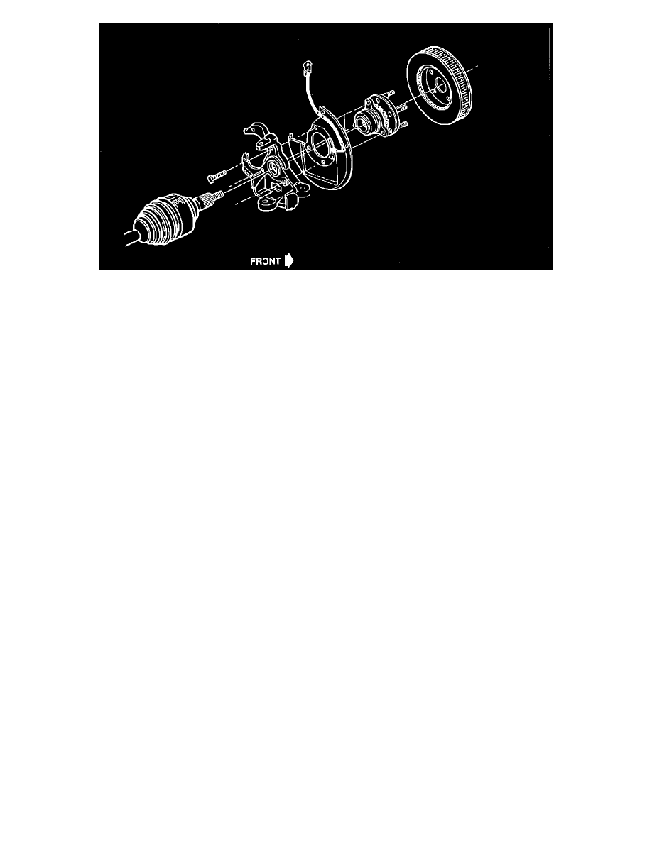
Front wheel hub/bearing assembly for 4WD vehicles.
Rear axle shaft for both 2WD and 4WD vehicles.
^
A magnet/coil pickup that mounts to the:
Front steering knuckle/splash shield.
Rear axle housing flange/backing plate.
^
An air gap between the toothed ring and the magnet/coil that is approximately 1.27 mm (.05 inches) and is not designed to be adjusted
As the teeth of the sensor move past the magnetic field of the sensor, an AC voltage signal is generated. This AC voltage increases or decreases
proportionally to the speed of the wheel. The ECU monitors this signal to check for a sudden change in single or multiple wheel deceleration rate(s). If
the deceleration(s) is (are) not within a predetermined amount, antilock intervention is necessary.
Each wheel speed sensor generates an AC signal in its coil. Each sensor circuit has 1000 to 22000-ohmresistance.
The ECU will disable antilock control, complete the "Antilock" light circuit, and store trouble codes if it detects the following conditions with any or all
of the wheel speed sensors:
^
Incorrect circuit resistance when checked with no vehicle movement (the ECU will "latch" these codes after the first brake application above 8
mph)
^
Incorrect sensor voltage output during vehicle movement (the ECU detects no signal when vehicle speed is above 8 mph)
^
Erratic sensor voltage output during vehicle movement