
Bravada V6-262 4.3L VIN Z (1991)
Wiring Diagram For Chart C-1A - ECM QDR Check Procedure
ECM QDR CHECK PROCEDURE (CHART C-1A)
CIRCUIT DESCRIPTION:
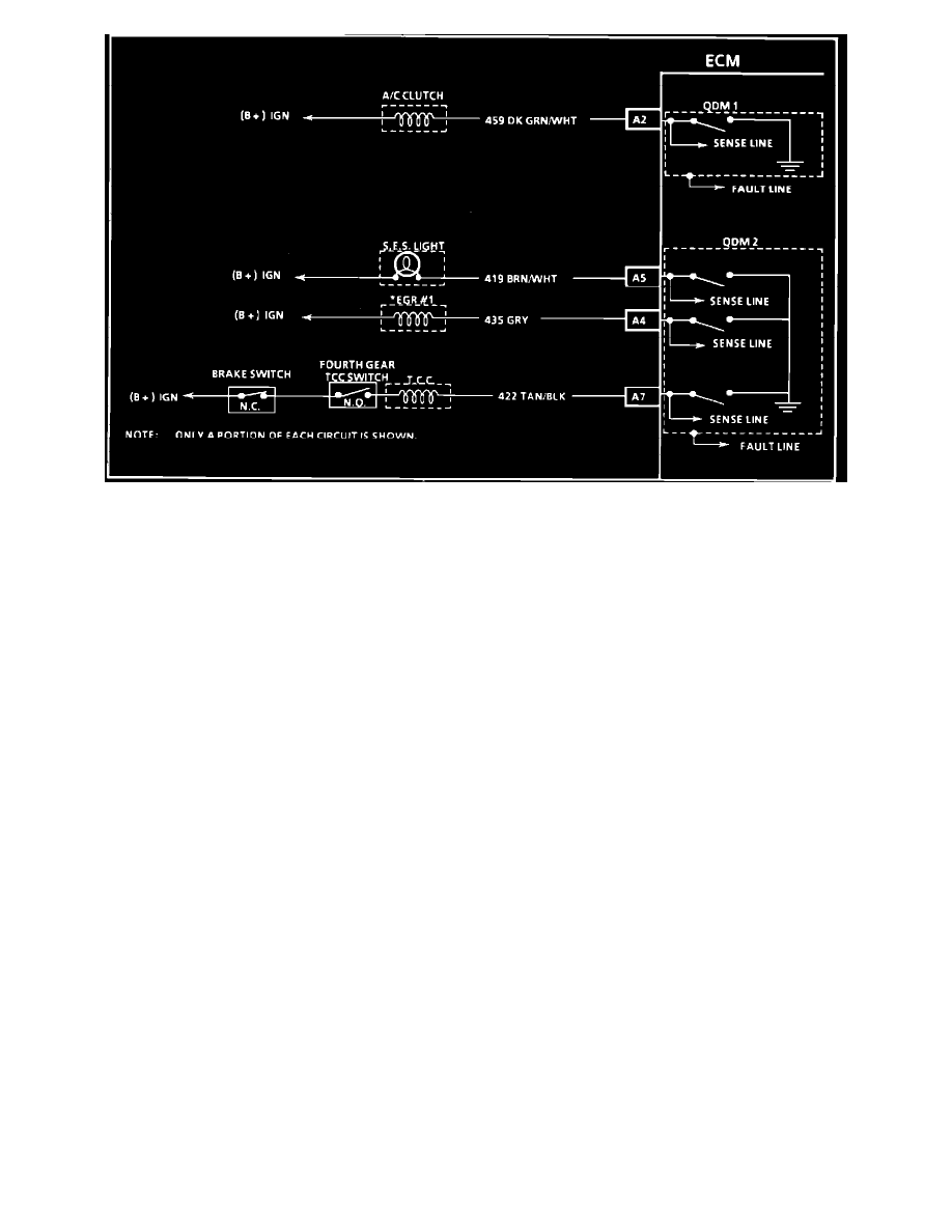
The ECM controls most components with electronic switches which complete a ground circuit when turned "ON." These switches are arranged in
groups of 4, called Quad Driver Modules, which can independently control up to 4 outputs (4 ECM terminals, although not all outputs are used). When
an output is "ON," the terminal is grounded and it's voltage should be low. When an output is turned "OFF," it's terminal voltage should be high, except
for the TCC control, which should also be low if the brake or 4th gear TCC switches are opened.
Quad Driver Modules are fault protected. If a relay or solenoid coil is shorted to voltage, it would allow too much current. The Quad Driver Modules
sense this, and it's internal resistance increases to limit current and protect the Quad Driver Module. The result is high output terminal voltage when it
should be low. If the current from B+ or component is opened, or the driver side of the circuit is shorted to ground, terminal voltage will be low, even
when output is commanded "OFF."